Author |
Message |
Michael Pikula
Industry Professional
|
Posted: Wed 27 Apr, 2011 3:23 pm Post subject: My quest for pattern welded inlay (photo intensive) |
|
|
Well over a year ago I was talking with Tim Lison about our next project and he asked what I wanted to work on. I have been inspired by and really wanted to learn how to do pattern welded inlay so after a few emails we decided to give it a go and we decided to use the sword from the first post of this topic, http://www.myArmoury.com/talk/viewtopic.php?t...ilt+viking as the inspiration. I did some work, came up with a concept drawing which ended up looking as follows :
One heck of an idea for a first attempt but as one art professor once told me, "go big or go home," and I think she would laugh and say go for it, and sure enough the process started! There were several skills that I was going to have to develop in order for this piece to turn out. First off was getting pattern welded wire welded into a surface. I took a piece of scrap L6 that I had laying around and with a flex shaft machine I gouged out the lattic pattern, and cut up some pattern welded wire in the appropriate shape and pondered my next step. In the following thread, http://www.myArmoury.com/talk/viewtopic.php?t...iron+inaly there was some discussion going on about various techniques that could have been used, I decided to try sticking the wire to a hot steel bar coated in flux, with the intention of heating up the plate, then placing the cold wire on the plate and hammering them into place. I didn't use enough flux, and the pieces half stuck, half didn't. I decided to just place the wires in the grooves and heat up everything together, which ended up working fairly well.
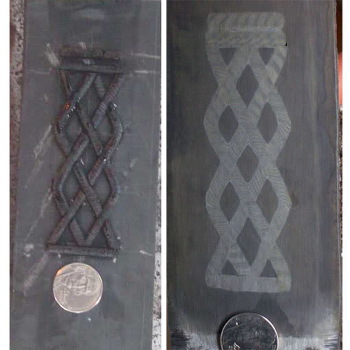
There was some modification that needed to be done, but for my first attempt, not shabby I think.
I moved on to forging a blank, and like before gouging out the lettering on one side, preparing letters, and forge welding everything together in a single heat. I annealed the bar, then gouged out the lattic pattern, prepared the wire, and welded everything together again.
At this point I'd like to apologize for not having pictures of every step. This has been a process that I've been working on for over a year and in the mean time I've changed cameras, switched computers, and dealt with a hard drive crash so some images you will have to use you imagination
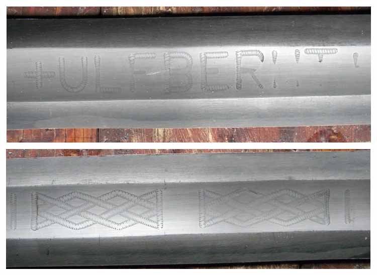
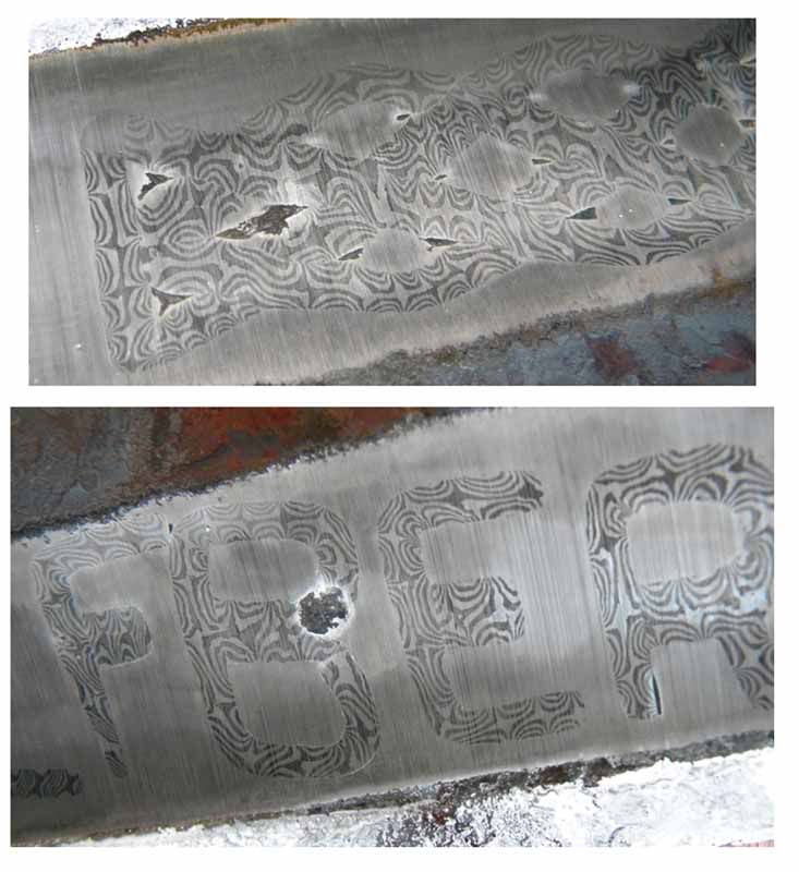
So everything was looking pretty good, and it was time for me to forge out the fuller which is a pretty daunting task when you consider the amount of time and effort that you are smashing away at. I did a decent job, but with the combination of not forging the fuller deep enough, and not accounting for the amount of distortion, and over grinding, the wire got ground through in several spots.
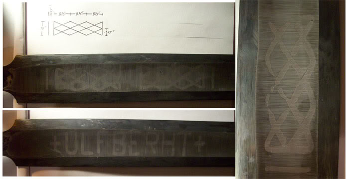
I felt like I was on the right track but I need to be able to control the depth of the grooves more consistently, and I wanted to have more control over the entire process. I knew that getting good grooves was very essential and I also knew that my skills at craving out these grooves was nowhere near where it needed to be. Plus I had a feeling that there were going to be many other bumps in the road and spending a week or so carving out grooves would add up to more waste then I would be able to afford. I did a little research and I decided to invest in a Pantograph engraving machine. With the Pantograph I was able to chisel in a pattern in one bar, and then follow that pattern by hand which moves a cutter, and making a channel. The pantograph machines work on a reducing scale so the pattern had to be larger then the actual size I wanted.
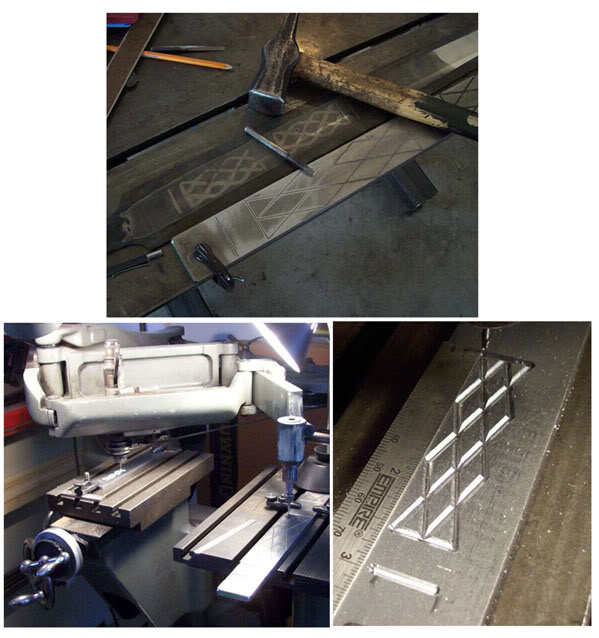
I got a good test piece, so then I moved on to my first attempt using the Pantograph. I went a little over board and order special cutter that would give me a rounded bottom, and a flared wall to ensure that all the flux got pushed out of the groove. I welded together a pattern welded billet and twisted up the thin rods to give me some wire.
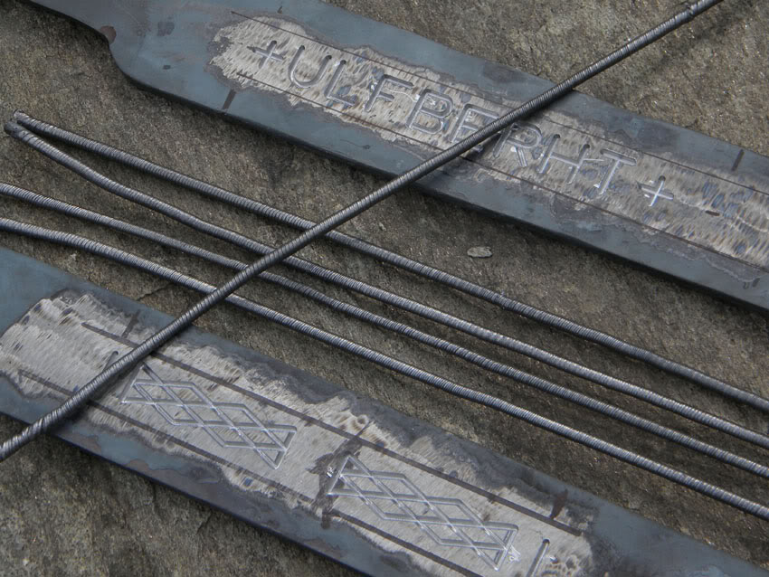
Next I had to make a special dye to profile my wire to fit the grooves. This turned out the be a royal pain, the taper was slight, but not large enough, and the wire kept sticking inside the dye.
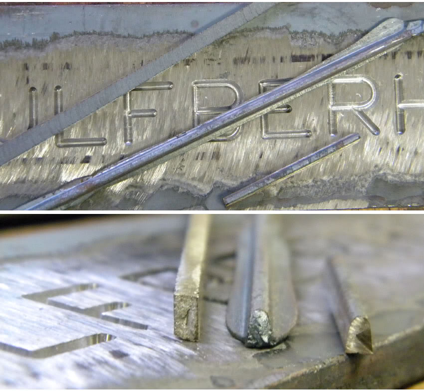
I was able to get enough wire profiled and I started setting the wire in the grooves. The one advantage of the profile that I chose was it was fairly easy to get all the mating surfaces of the wire to sit tight and snug.
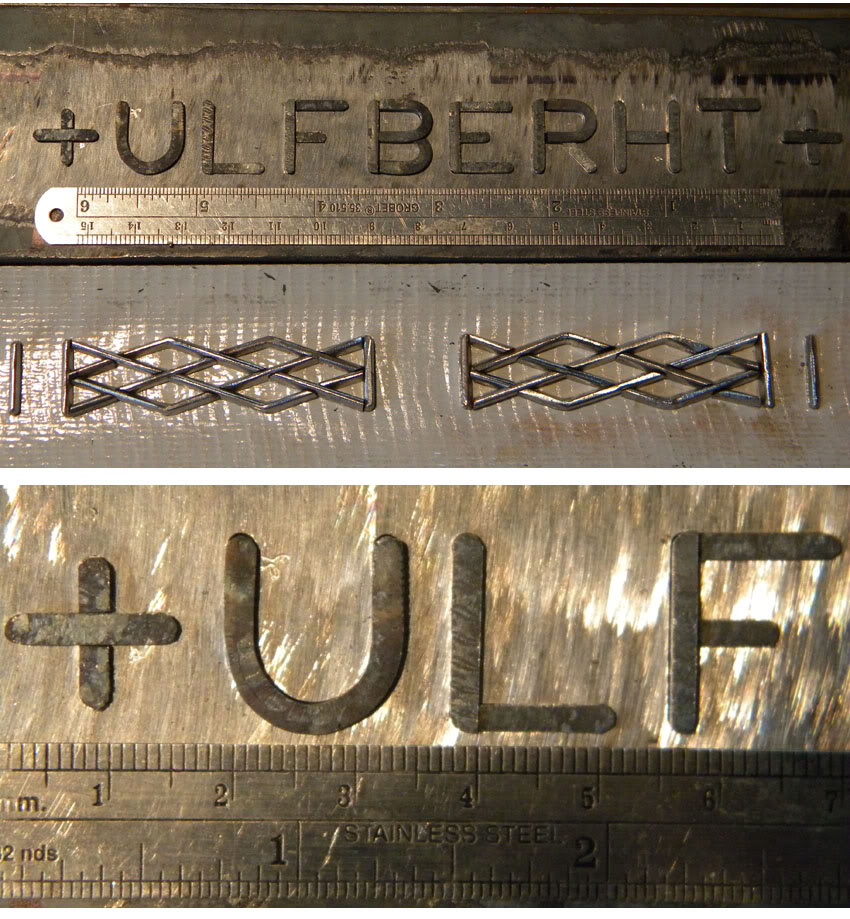
I decided I was going to do both sides at once since it seemed more reasonable, plus it was ensure that I had equal distortion on each side. I wanted to leave a little bit of the wire proud to give the wire a little extra material to push and fill the grooves. I hammered the sides of the grooved with a chisel hoping that the pressure of the pinch on the sides would be enough to keep everything in place. Slowly I brought the entire package up to heat, and right when the blank started turning red, pop pop pop went the letters. The blank was dead since scale had already formed, and the scale that forms on L6 is awesome at screwing up welds. The wire was on the bottom of the forge, so take two!
This time I came up with a clamp that would tightly hold the wire in place.
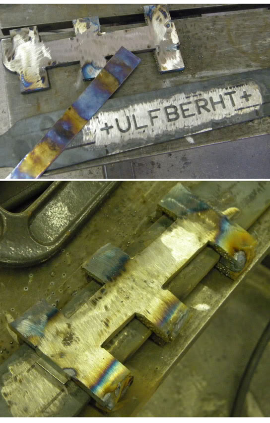
The thin sheet is oxidized nickel which I placed between the wire and the clamp so that the two wouldn't weld to each other. This turned out to work pretty well, after several welding heats I cut one edge of the clamp and peeled it of and the letters were nicely welded in place. I forged out the fuller, and gave the fuller a rough grind to find.....
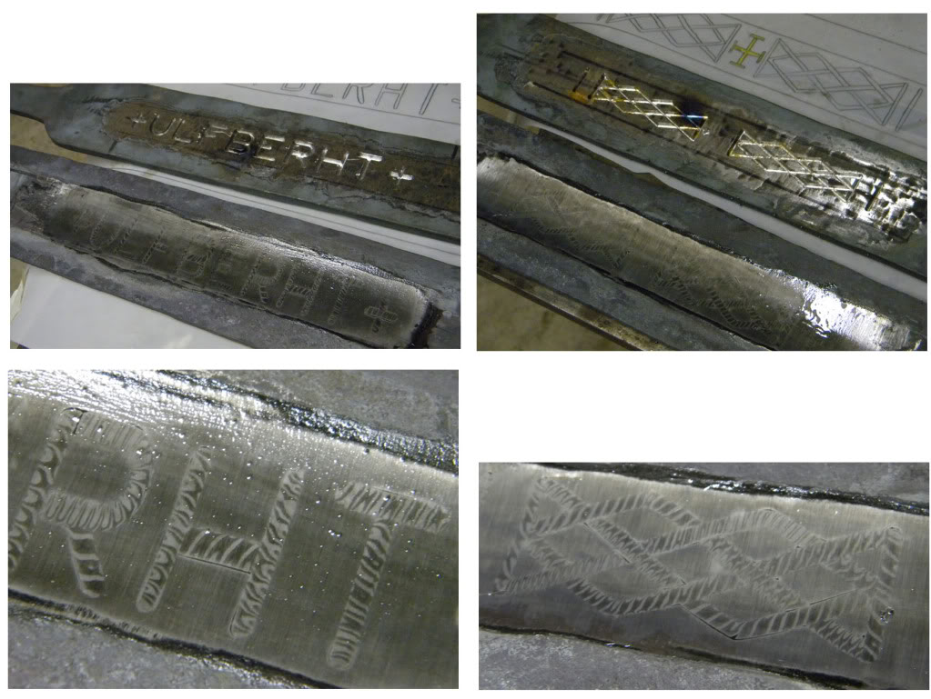
not exactly what I had hoped for.
But hey, things were getting better so let's do it again. This time I made a few small adjustments, I decided to make the channels round, and use round wire since sometimes keeping things simple is the better way to go. Plus I figured that the gaps were a result of not having the profile just right, and the clamp absorbing some of the welding blows and not giving the wire the "push" it needed, and seriously? Who wants to use a big honking clamp anyway? I figured in history metal was valuable and wasting it for that purpose might seem a touch out there. So again, I carved out the grooves, made some wire, and started setting the wire.
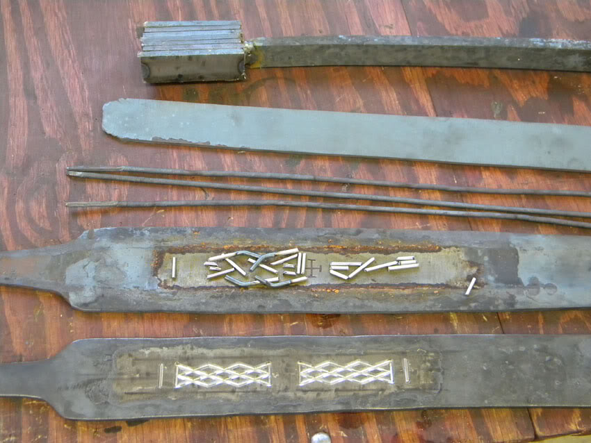
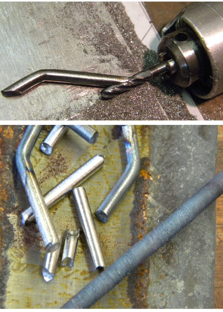
As I got started I ran into my first issue, I wanted to fit the wire together as close as possible, and just cutting the wire and grinding it straight would leave a gap on the inside of the groove. Hey, no problem, I just mounted my flex shaft on the table, and put a little piece of steel under it, and each piece was hand ground, and then profiled to fit.
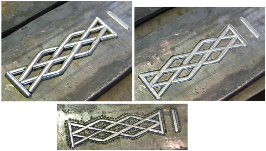
The lattic side in particular was a nightmare! The piece kept moving around and with each fitting they would bump out of place and slowly but surely they started coming together. When I thought I had everything to where it should fit. I clamped a bar over the top, took it to the power hammer, and gave it a good blow to sink all those little sucks into the grooves. Yahoo! They went in. With a center punch I went around the outside to close them in place with no chance of playing great escape. "Where you going? Nowhere!"
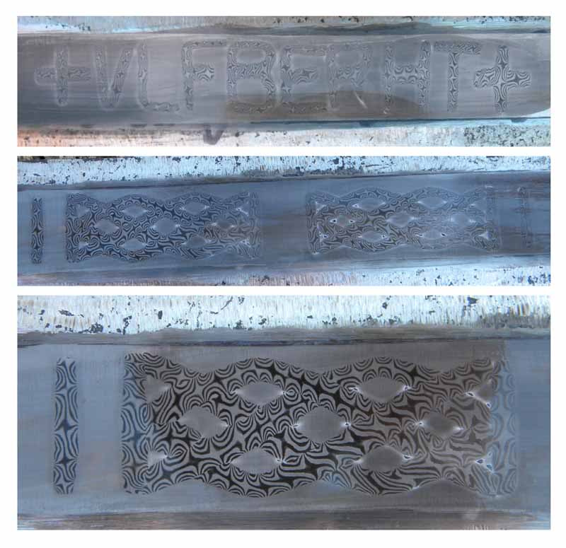
The welding went great, I thought. It turns out that I didn't leave enough of the wire exposed to get the push that I needed and I ended up with some rather awesome gaps. Well not awesome in a good way, but awesome in a big way. I'm beating myself up for not finding a picture to show, because there was one other issue that would have scraped the blade even if there were no gaps. The wire had to high of a layer count and it was twisted too tight. The resulting pattern didn't look anything like what I was going for.
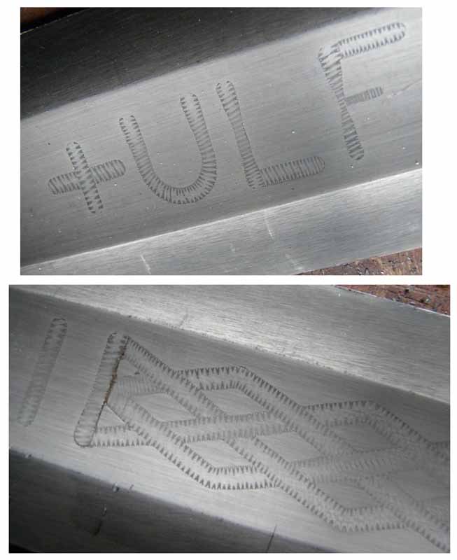
However all of this did give me a chance to practice up my grinding of the blades. I found the weight of the original, and so I ground the the two pantograph engraved blades to test the weight , balance, and diameter wheel to use. I used a 10" wheel on the first blade, and a 6" on the other. The 6" proved to be too deep, cutting though the wire in some points, and leaving too high of a ridge and too much mass at the tip to balance out the blade and hit my target weight. The 10" wheel gave much better results and the thin, wide blade had the right balance and feel for what I needed. Incidentally the gaps diminished a great deal, and with the final grind the blade turned out fit for sale. http://www.myArmoury.com/talk/viewtopic.php?t=20326
I did talk with Tim and I requested that I change gears and approach the project from a different angle since there were still factors that I wanted to address and while the blade ground with the 10" was good, I wanted to do better. I felt that the wire was a touch thin for what I was hoping for, the pattern was too distorted from the re-profiling of the wire in the dye, and while I could live with those slight gaps, I was sure that I could do better.
I'll post the next leg of my quest tomorrow or the following day. These hands need to go get some dirt on them
|
|
|
|
Stephen Curtin
|
Posted: Wed 27 Apr, 2011 4:10 pm Post subject: |
|
|
Incredible work michael, can't wait to see more. Tim sure is building up an impressive collection.
Éirinn go Brách
|
|
|
|
Tim Lison
|
Posted: Wed 27 Apr, 2011 8:48 pm Post subject: |
|
|
Michael has been really amazing to work with throughout this project. We both knew this was an ambitious project going into it. I know he wanted to learn this skill and I certainly want the end product but it's been a really interesting look into what goes into making a sword. Michael has sent tons of photos along the way. His dedication to getting this skill right is amazing. I'm really glad to have helped facilitate it! I really like that he's doing a progress thread. Not only does it benefit those customers who want to learn about this technique, but any industry professionals who view it can benefit from Michael's trail and error/ success. I'm glad to have been a small part of that! I certainly hope to see more swords with blade inlay being made. I think it "ups the bar" in both authenticity and appearance for many swords. I look forward to more photos of this project as Michael posts them!
|
|
|
|
David Huggins
|
Posted: Wed 27 Apr, 2011 9:09 pm Post subject: pattern inlay |
|
|
Brilliant to see work in progress. Thanks to both Michael and Tim for sharing.
best
Dave
and he who stands and sheds blood with us, shall be as a brother.
|
|
|
|
Johan Gemvik
|
Posted: Thu 28 Apr, 2011 5:58 am Post subject: |
|
|
I always wondered how this was done. Great project!
"The Dwarf sees farther than the Giant when he has the giant's shoulder to mount on" -Coleridge
|
|
|
|
Michael Pikula
Industry Professional
|
Posted: Tue 03 May, 2011 1:34 pm Post subject: |
|
|
Thanks for the replies so far!
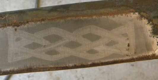
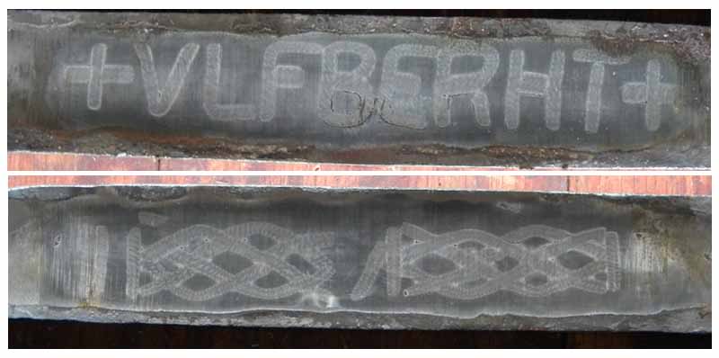
I was able to reclaim the last blade from the first series of attempt and took some pictures to document what was going on.
At the time I didn't know what what going on, or why the welding wasn't turning out. At this point I had a bit too much time invested in tinkering around with these small little pieces and trying to get them to fit just right and not having the results that I was looking for. I know that in period time was the cheapest expense, but somehow I didn't feel like this was as efficient as I imagined the process might be....
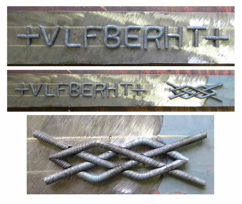
My new direction took me toward arranging the characters on a hot bar, glued by flux, and hammered into a blade blank at welding heat, and then completing the weld. I had no clue how this was going to turn out so naturally I did another test piece. I arranged a lattic pattern on the anvil, heated up a piece of flat stock, gave it a good coating of flux and pressed it onto the wire, hoping it would stick. I got most of the piece stuck, but a few moved, and a few squirmed around a little. I was able to manipulate them back into place while the bar was still hot, and then heated up a piece of W2 to weld them into. The welding process went okay, I ended up doing more forging then I would have liked to get everything to close up, and there was a little movement in the wire. Overall I thought I could work with the process and decided to proceed in this direction.
I preped up a full set of letters and started working on the lattic pattern. Since I figured there would be a lot of movement on the part of the lattic I decided to make four pieces, each with a bend, and then interlocking grooves cut into the wire to give me a solid piece to weld and limit the movement as much as possible. Getting this right was a royal headache, but necessary if I wanted to cut down on my margin of error.
So I heated up some two bars, one for the lettering, one for the lattic. I included nubs on the end and one side so that I had a reference point to line up the bar with the blade blank. I hammered the lettering in, and all seemed to go well. I gave a good welding pass after to ensure everything would stay put, and then wire brushed the back end to prepare the surface for the lattic. The lattic did not cooperate at all...
The slight difference in the height between the lattic and the vertical bars caused the wire to shift. Also the very thin section that was left to hold the lattic together didn't survive in every joint. There were still a few welding "flaws" but compared to my best attempt with the grooves I felt that there was more success. So time to tweak the process and come up with a better technique using the same method.
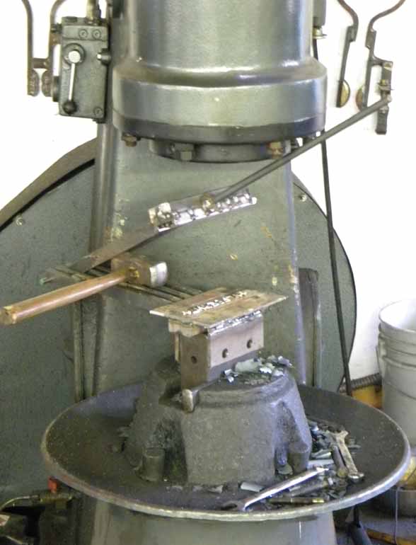
Being a one person shop and not having access to anyone to do some decent striking or lend a hand I turned to Molly for a little help. I made a tool that consisted of a platform, and a top bar that can hold blanks.
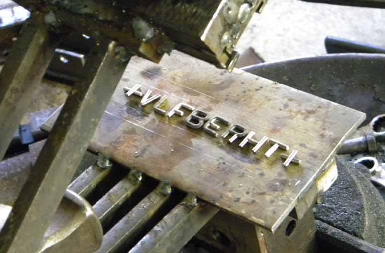
The way it worked was I would lay out the pattern to be inlayed on the platform, and then heat up a bar, coat with flux, and insert into the top bar. Then pull the handle down, clamping the hot bar to the wire, and giving a gentle thump to set the wire a tiny bit into the hot bar, and let the flux grab the wire in the process. Then insert a blade blank, clamp down the bar that had the wire "glued" in place and give a couple really good knocks and set the wire in the blank creating a groove under then wire and then weld it all in place. I thought that this compression of the wire into the groove would help create a better mating surface between the wire and the blade blank, and giving me a better weld. So how did it work in a practical application.....
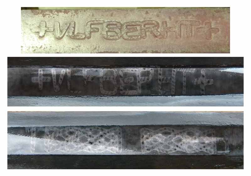
Well first off getting the letters to all set and glue into the top bar was pretty difficult. Any slight variation in height sent the wire moving and once the top bar got hit to set the wire into position the only way to correct them was to knock off all the letters, grind the oxidation off, and try again, and again, and again until I got a bar that had all the bits of wire held in their proper position. So now, off to welding, I heated up a blade blank, and hammered the wire into place, then the lattic, and while not perfect, I felt like I was on the right track....
There was a spot on the B that didn't weld all the way, and the back side of the lattice had a bit too much funk in the surface but the flow of the letters, the organic feel, everything sticking together and no pieces shifting was a small success in my book. To ease the next attempt along I made a few simple changes. First I made a template for the wire to sit in by engraving a plate for them to sit in prior to getting stuck to the bar to be held in place. Which turned out to work fairly well, there was still lots of tinkering, and in the end it turned out that if the letters didn't stick on the first try the most, dare I say, efficient way was to pitch it and use a new set. Reheating the bars, resulted in the flux flaking off the bar taking the wire with it, or letting the flux travel and coat the wire which resulted in gaps due to hard flux forging grooves when setting the letters, which don't end up getting filled, and a whole bundle of other problems. Secondly I decided to use W2 for the blade since it is easier to forge, easier to weld, and I thought that it would work much better then the tough L6. So how did it go?
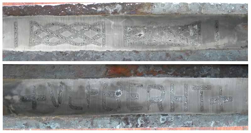
Not horribly shaggy. The blade was boarder line and I would have to do my final grind on it to see exactly when I ended up with. In the end however the results failed to be pleasing.
The lettering turned out great, with the exception of grinding through the bottom of the L, and the leg of the R. The lattice was littered with pits at every intersection and tight joint. Also I noted that there was more distortion on the letters which got more welding heats and hits then the lattice. While I think that the slight pitting could have been resolved, or covered up, using powder abrasives for finishing work, the grind through issue was not acceptable. In the diagrams that I've looked at, and pictures I've seen there doesn't seem to be any evidence of blades that had a point or two ground through. The one cross section of an original inlay that I've seen clearly shows almost half the wire sitting below the surface.
So I decided to scrap this method and start brainstorming my next course of action.
Part 3 to follow.....
|
|
|
|
Tim Lison
|
Posted: Tue 03 May, 2011 2:34 pm Post subject: |
|
|
Well, they're looking cool! I know it's not quite there yet, but will be soon. Keep up the good work Michael!
|
|
|
|
|
You cannot post new topics in this forum You cannot reply to topics in this forum You cannot edit your posts in this forum You cannot delete your posts in this forum You cannot vote in polls in this forum You cannot attach files in this forum You can download files in this forum
|
All contents © Copyright 2003-2024 myArmoury.com All rights reserved
Discussion forums powered by phpBB © The phpBB Group
Switch to the Basic Low-bandwidth Version of the forum
|