| Author |
Message |
Etienne Hamel

Location: Granby (QC) canada Joined: 09 Sep 2006
Posts: 443
|
 Posted: Sun 10 Jan, 2010 6:32 am Post subject: Posted: Sun 10 Jan, 2010 6:32 am Post subject: |
 |
|
so riveting or wielding now thats the question  i can't decide... anyway my desing need more work as it is a rough sketch. i can't decide... anyway my desing need more work as it is a rough sketch.
|
|
  |
 |
|
Ken Nelson
|
| Posted: Sun 10 Jan, 2010 6:39 am Post subject: |
|
|
I am on the fly right now, so I will try to post a better, or longer, response later.
Maurizio, you do bring up an interesting point, and I would like to examine the pictures in context. Could you please tell me where you found those pictures? To me it looks like a piece of cold worked mild steel was used and then welded. it appears to be pearlite/ferrite banding due to drawing or cold rolling.
"Live and learn, or you don't live long" L. Long
|
|
 |
|
Maurizio D'Angelo

|
| Posted: Sun 10 Jan, 2010 8:19 am Post subject: |
|
|
Hi Ken,
The photo shows a welded joint, is highlighted on its structure.
In a site specializing in research and development is written: "The use of welding is generally prohibited in the area where the plastic hinge develops in ca by inducing embrittlement in the base material of the armor, even if it is required that the steel reinforcement is weldable (EC8). In fact, the welded joints of the head between two bars have shown, even with the best welding conditions, a satisfactory behavior in terms of resistance of ductility under monotonous loading, while there has been a very poor behavior in terms of life in low cycle fatigue. Their application in the area where the plastic hinge develops is far from commendable (Franks et al. 2001)."
http://www.buildup.it/Portal/index.asp?locati...;template=
It also puts much emphasis on the arrangement of fibers for the duration of the joints in terms of undulations.
I think that even today, on airplanes, the pieces are subjected to large bending rivets. There is no need of weapons, but it serves to support the concept.
Remember reading that the swords were welded to helical twisting bars, right or left, to make stronger their resistance. In practice, not knowing this, the fibers of the material disposed in a line in favor of resistance.
I think you'll agree that the arrangement of the fibers affects the fatigue resistance when a piece tends to vibrate.
Ciao
Maurizio
|
|
 |
|
|
Ken Nelson
|
| Posted: Tue 12 Jan, 2010 4:06 pm Post subject: |
|
|
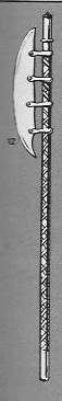
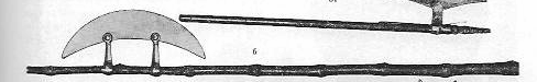
Greetings, this will be a two part post, a couple of pictures and then more welding talk.
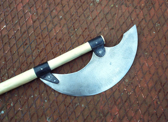
I found two pictures of riveted weapons resembling berdiches or voulges, however, both turned out to be long hafted axes from India. Unfortunately, not the area that I was hoping.
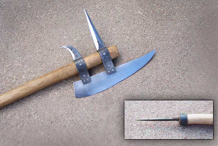
I have also found two pictures of modern reproductions that use rivets.
On the welding of high carbon to low carbon or iron, The ASM Metalss Handbook series, Vol 6, welding and brazing page 2184 states:
The literature on steel includes the bonding of high-speed steels to carbon steels for prismatic cutting tools (Ref 25) and
the joining of pure iron to a range of carbon steels (Ref 26). In this latter work, the bond tensile strength was greater than
430 MPa (62 ksi), which exceeds that of the weaker parent metal. A slight increase in tensile strength occurred with a
decrease in welding temperature from 1000 to 900 °C (1830 to 1650 °F).
Which means that if there was to be a failure due to strength, it would be on the low carbon or iron side , not the weld, not the high carbon part. Iron and low carbon steels generally have a tensile strength of 60ksi or 420 MPa and the high carbon steels can exceed 320ksi, or 2100MPa.
I asked specifically if the pictures you posted earlier were cold worked steel, because of specific properties. as the link you posted does not have the pictures, I cannot see what was done before or after the weld. I mentioned that it appeared to be ferrite and pearlite bands. this does NOT exagerate as the carbon content rises, infact, it lessens. As the carbon content rises, there is more pearlite in the steel, and less ferrite. at .77% carbon, you now have 100 percent pearlite, and no ferrite left in the steel. Also, I wanted to know what temperature and what length the steel was held at that temperature because if the steel was allowed to fully recrystallize, the banding on the left side would not be visible. I do see that it is softened, but it hasn't entirely disappeared.
Again, I feel that there are a few misunderstandings in terminology. Modern steel, does not have any fibers. it has a grain structure, and those grains can be stretched, but unless you are dealing with old wrought iron, or a backyard smelt, there are no fibers in steel. the fibers that were in wrought iron were mostly made of the impurities. Having fibers in modern steels would only weaken them, as it would mean there are impurities in the steel, or voids. For a comparison, let us look at a steel cable. A cable has "fibers" each one being a steel wire, which is solid. Let us assume for the comparison, that a rod has been made from the same material, and has been subject to the same working and heat treat. Cables are great because the small diameters of each wire allows them to be flexible. a 1" (25mm) steel cable is capable of being wrapped around a spindle of a crane for lifting, a round bar of the same diameter, would not be. however, if you were to pull each one the cable would break at a much lower load than the solid bar. the air between the fibers does nothing to strengthen it, and allows the fibers to rub and wear against each other.
The other term that was brought up tells me that the study you referenced, does not directly affect what we are discussing with welding on weapons. That term is "plastic" When you push on a bar of steel, like a blade, deforms, or moves. there are two different types, elastic deformation, and plastic deformation. Elastic deformation can be referred to as flexing. When a bar flexes, it will return to true when the pressure is removed. this is normal, and causes no permanent damage. When a steel flexes, it shows that it has enough strength to resist. Plastic deformation is bending. once enough force is applied to bend the metal, it is damaged, it will no longer return to true. it will stay bent. you can bend it back and try to straighten it out, but the damage has been caused. When you mentioned plastic hinges, that means that the metal is being pushed too far, it is being bent, damaged. Harmonic vibrations that occur in swords are well in the flex range, not the bending range. Bending a piece back and forth, will often cause it to break at a point where stresses can rise, or there is a change in strength. for example, if you were to place a piece of steel in a vise and clamp tight then bend it back and forth, the crack that forms will probably be at the jaw. where the metal contacts the sharp edge of the jaw, the stress will build. if you were to use softer jaws, but had 1 scratch left over from a 36 grit belt, chances are the crack would start to form at the base of the scratch. If you were to put a welded piece in the vice, where it would crack would be determined by strength of the materials, thickness of the materials, and if there were any residual stresses form the welding. If properly done, the crack on a high carbon to low carbon steel would start on the low carbon steel, perhaps right next to the weld, as there may be a little more resistance(62ksi vs 60ksi), but in the mild steel, not the weld.
And as for the airplanes, the only rivets I know of in the planes I worked on were the ones used to hold the padding to the seat for the pilot's comfort. all critical joints were welded(frame, wings, mounts for the engine) Bending rivets is a recipe for disaster, as if you bend any steel enough times, it will break.
 Attachment: 13.48 KB Attachment: 13.48 KB
Attachment: 21.53 KB
Attachment: 78.35 KB
Attachment: 88.43 KB
"Live and learn, or you don't live long" L. Long
|
|
|
|
|
Maurizio D'Angelo
|
| Posted: Tue 12 Jan, 2010 8:24 pm Post subject: |
|
|
Ken,
You're right for the translation of the fiber, it is fair to say grains. (but, in italian grain = wheat ).
There are two ways of connecting the pieces: a rigid, welding. The other non-rigid, bolts or rivets. For flexible parts, the second is better.
I'd like to deepen the discussion with you, I'm sure we will learn both. But your language is a problem for me.
Now airplane.
Never an Italian plane crashed. No, I'm wrong, one in Ustica. A missile accidentally fired from NATO ships.
The takeoff is optional, landing is mandatory! kidding
Many structures are built in an airplane aluminum (Aluminum 2024-T3) other in Ultra High Strength Steels (2500 MPa maraging steel 300M).
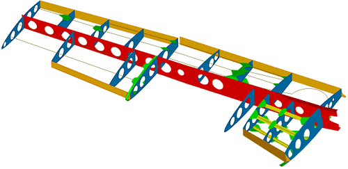
Evaluation of the structure of an aerobatic plane.
The wing is fastened to the fuselage structure at three locations. These joints transfer load from the
front, main and rear spars. The main spar was modelled clamped to the fuselage, this is close to reality
due to the high stiffness of the fuselage spar box. The front and rear joints were modelled as pins,
allowing only rotation about the main axis of the bolts.
The acceleration of the structure and the fuel weight were applied as distributed loads.
The finite elements model yielded coherent results, well within the required certification[3] safety
factor of 1.5. The maximum von Mises stress reaches 24 ksi. The yield stress for 2024-T3 Aluminium is 53 ksi.
The front and rear joints must be the object of further analysis since the global finite elements model did not accurately represent neither their geometry, nor the interaction with the fastening bolts. Nevertheless, the computed reactions at these locations should be close to reality, as they depend mainly on the flexibility of the whole structure.
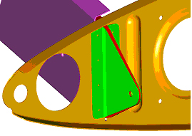
According to the global finite elements model, the most stressed elements are the attachment plates.
The main plate and two reinforcement plates are identified in Fig. 11.
A two-dimensional finite elements model was constructed using a single mesh to represent the
thickness of the three plates. The applied load was the reaction force computed in the global finite
element model. The out-of-plane load was small enough to be neglected. The plates were modelled
clamped to the rest of the wing structure. These are the areas where the maximum traction stresses are found.
Federal Aviation Administration (1998), Damage Tolerance and Fatigue Evaluation of Structure.
FAR 25.571.
The authors take this opportunity to thank Dr. James C. Newman, Jr. in the Mechanics of Materials
Branch at the NASA Langley Research Center, for his support.
This is not to say that airplanes do not run welds, I just say that some parts are fixed with bolts , screws and rivets. These stuff are special, not common. Micro-sub-structural cracks are beginning, from the holes of the link. Difficult by bolts or screws.
Welded sword will not break ever on your welding, but immediately before or after it. The weld can be stronger than the material itself, on this we agree.
Etienne, and other readers, thanks for your patience.
Attachment: 61 KB
Attachment: 99.21 KB
|
|
|
|
|
Jean Thibodeau

|
| Posted: Wed 13 Jan, 2010 7:14 pm Post subject: |
|
|
Maurizio and Ken your last two posts are very informative, at least to the degree that I can understand the complicated technical issues.  
But what I think I get from it is that:
1) The high carbon steel won't cause a problem.
2) The weld if well done will be very strong but maybe weaker than the high carbon steel.
3) That the low carbon steel will be the weakest link in the assembly and would fail before the other two.
With an aircraft this weakness would be a critical issue as sustained and repeated stress/vibration(s) would eventually cause this part to fail putting lives at stake and wouldn't be acceptable in the design of an airplane.
With a halberd using welded on low carbon steel the low carbon steel may be the weakest part but may still be stronger than the stresses it would be subjected to by normal human strength.
Also the low carbon steel sockets/eyes may not have the tensile strength of the heat treated high carbon steel but can be made very strong by being made very thick ( or at least thick enough to not be bendable ..... no bending or plastic deformation then no damage or accumulated damage ).
So I'm just saying that although the issues of margins of safety in the design of an aircraft are fully valid in a theoretical sense they may not be critical when making a halberd if the weakest link is still strong enough to not fail under the maximum stresses that it might have to face if one hit something hard repeatedly.
You can easily give up your freedom. You have to fight hard to get it back!
|
|
|
|
|
Etienne Hamel
Location: Granby (QC) canada Joined: 09 Sep 2006
Posts: 443
|
| Posted: Wed 13 Jan, 2010 7:50 pm Post subject: |
|
|
|
is 1/4'' thick sockets would be ok if i use iron or low carbon steel?
|
|
|
|
|
|
Aleksei Sosnovski
|
| Posted: Thu 14 Jan, 2010 12:45 am Post subject: |
|
|
| Etienne Hamel wrote: | | is 1/4'' thick sockets would be ok if i use iron or low carbon steel? |
As far as I remember most halberds I have seen used in historical reenactment were made from 3-4 mm thick steel, which is 1/8" to 1/6". So 1/4" should be more than enough. However the thickness of the metal is not the only thing that matters. Width of the sockets is also obviously important.
Regarding welding. I have some experience with welding high-carbon steel. From what I saw the thing that usually breaks is neither the weld nor the low-carbon steel part (which is flexible and therefore cannot break unless you flex if enough times which in our case is impossible), but the high-carbon steel on the weld margin. As far as I understand that happened because of improper welding process (the steel got quenched around the weld and therefore became brittle). Therefore I would recommend following procedure for welding the sockets:
1) preheat the pieces before welding
2) thoroughly anneal/normalize the piece after welding
3) quench only the cutting edge, leave enough unquenched steel between the quenched part and the welds. DO NOT QUENCH WELDS!!!
4) Use plain old carbon steel, do not use alloy steel (unless you are absolutely sure that it is weldable, that is).
5) Use steel with as little carbon as possible. 1040 or 1045 will give you a reasonably hard edge for cutting soft and medium targets (actually I think it will be MUCH harder than blades of most originals) and at the same time will cause minimum problems during welding.
6) Use welding materials specifically made for welding high-carbon steels. Ordinary welding rods/wire most likely will not work well.
7) Make welds as long as possible. If something will break, than it will be either the weld itself or the high-carbon steel along the weld. The longer the weld, the less likely it will break.
P.S. Please correct me if I am wrong.
|
|
|
|
|
Maurizio D'Angelo
|
| Posted: Thu 14 Jan, 2010 3:51 am Post subject: |
|
|
My conclusions:
To make a weld on a halberd, I'd use a steel with low carbon content. There are many steel, other alloy components, equally strong, easily solderable, they also facilitates the heat treatment. Aren' t only the steel 1045 or 1075 but also many others. (These acronyms are American, not European)
If you just want to use a steel with a high carbon content, choose a welder who has knowledge of Ken, a blacksmith random could easily go wrong. For thicknesses halberd, those historically plausible.
Ciao
Maurizio
|
|
|
|
|
Etienne Hamel
Location: Granby (QC) canada Joined: 09 Sep 2006
Posts: 443
|
| Posted: Thu 14 Jan, 2010 10:02 am Post subject: |
|
|
|
i think i'd go for the riveted version beacause it seems less things to take care of and they look bad ass so iron sockets riveted to the 1075 carbon steel blade is my choice now i must find the money
|
|
|
|
|
Maurizio D'Angelo
|
| Posted: Sat 16 Jan, 2010 5:56 am Post subject: |
|
|
Hi all,
even if totally off-topic, I write this because he had been raised some doubts about the structure of the aircraft. All of us happen to fly. Knowing where we sit when we're up there can be more reassuring.
I built a few and insignificant pieces for a well-known Italian manufacturer of aircraft and not in Grottaglie, I received a reply from Aeronautic Structural Engineer, we feel at times for some clarification.
The fuselage, wings and many structures are made of aluminum with small thicknesses, are riveted, (some with bolts and screws). Welding in Aerospace, is used, just the bare minimum. An imperative is the lightness. Who commissioned aircraft, get paid, but not the weight of the plane, the always travel free, but the cargo, the latter is what pays. All pieces are also very complex derived from the solid material, also work at 95% on machining centers. Weld creates too many problems, the inflections are a risk to the supporting structures, a plane PARKING in Cairo, has 50 degrees in the air flying over Siberia -30 ° to even more rigid structures can not endure these changes, the phenomenon is known as thermal corrosion. To limit these phenomena, the welds would be very expensive, even for the controls. Today, we are adopting new composite materials, many are glued in a vacuum ...glued???  Yes glued. Yes glued.
that God send us good.
Knowing this, now everyone will fly to sleep easy... a prayer can not hurt. 
P.S.
Dan, the rivets do not work well only on the coats of mail.
Ciao
Maurizio
|
|
|
|
|
|
|
You cannot post new topics in this forum
You cannot reply to topics in this forum
You cannot edit your posts in this forum
You cannot delete your posts in this forum
You cannot vote in polls in this forum
You cannot attach files in this forum
You can download files in this forum
|
All contents © Copyright 2003-2024 myArmoury.com — All rights reserved
Discussion forums powered by phpBB © The phpBB Group
Switch to the Basic Low-bandwidth Version of the forum
|