Brilliant. Looking forward to seeing the finished work.
| J Helmes wrote: | ||
Hi Dan, Sorry to jump topic here but could you please share some of these studies with me, or point me in the right direction. I flat out don't buy it. Aren't those "slag" stringers made of what is essentially glass? If I'm about to change what I tell people about the weathering properties of wrought iron I'd like to be able to back it up properly. Thanks, Jeff |
There was a large discussion on the arch-metals mailing list few years ago
ARCH-METALS@JISCMAIL.AC.UK
They presented more than enough evidence to convince me but I'm not a metallurgist.
| Johan Gemvik wrote: |
|
One new detail Niclas got from Vegard was that the rivet dome has a double bulb, one on top of the other. You can clearly see it in the photo on the excellent (but short overview) Hurstwic site. On the middle of this webpage: http://www.hurstwic.org/history/articles/manu...g_mail.htm Or here: [ Linked Image ] Incidentally I found several of my own riveted links have the same shape. I've been trying to work that off them, but clearly I shouldn't. In fact when I make my next riveting plier set I'll make two, one with a large dome for first stage crimping and another second one with a smaller recess for second stage to shape the top bulb. |
I don't get it - what is so special about the double bulb? I believe it happens when the dome created by piercing the ring differs from the depression in the rivet setting pliers. I also get this effect constantly when I use my older pliers that have some wear in them.
You have done good work developing the punched ring prosess for the gjermundbu mail Johan. Interesting to see the presentation here. There is one detail of the process that I was not aware of when i wrote my little paper "Brynjevev/Ring weave". I discovered it during later studies. I will share it with you here shortly so that you have the opportunety to perfect the prosess.
I agree with you Andris, there may have been a misunderstanding. The double dome is not the result of setting the rivet twice with two different sized peening depressions. It is the result of the hole for punching/drifting beeing slightly larger in diameter than the depression for the peening of the rivet. The rivets used for the gjermundbu mail is almost round in cross section (and somewhat conical in shape). The hole for punching/drifting has therefore also been round.
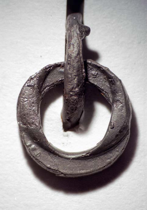
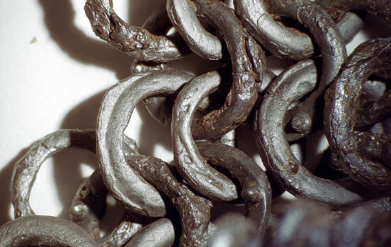
There are also other interesting toolmarks on the rings. They are not present on all the rings (that includes the double dome), and are not equally common, but they can be found frequently on the best preserved riveted rings from the gjermundbu grave find. (By the way. Notice the backside of the rivet area. The rivet is flush with the ring material, and there is no visible transition between the metal of the ring and the rivet. This quality is quite common on period mail as I can remember, but few are able to reproduce this today, so we are doing something wrong).
[ Linked Image ]
[ Linked Image ]
 Attachment: 133.38 KB
Toolmarks on riveted mail rings from the gjermundbu mail [ Download ]
Attachment: 207.55 KB
Riveted rings, gjermundbu mail [ Download ]
| Andris Auzins wrote: | ||
I don't get it - what is so special about the double bulb? I believe it happens when the dome created by piercing the ring differs from the depression in the rivet setting pliers. I also get this effect constantly when I use my older pliers that have some wear in them. |
I agree with you Andris, there may have been a misunderstanding. The double dome is not the result of setting the rivet twice with two different sized peening depressions. It is the result of the hole for punching/drifting beeing slightly larger in diameter than the depression for the peening of the rivet. The rivets used for the gjermundbu mail is almost round in cross section (and somewhat conical in shape). The hole for punching/drifting has therefore also been round.
There are also other interesting toolmarks on the rings. They are not present on all the rings (that includes the double dome), and are not equally common, but they can be found frequently on the best preserved riveted rings from the gjermundbu grave find. (By the way. Notice the backside of the rivet area. The rivet is flush with the ring material, and there is no visible transition between the metal of the ring and the rivet. This quality is quite common on period mail as I can remember, but few are able to reproduce this today, so we are doing something wrong).
[ Linked Image ]
[ Linked Image ]
Toolmarks on riveted mail rings from the gjermundbu mail [ Download ]
Riveted rings, gjermundbu mail [ Download ]
Last edited by Vegard Vike on Sun 28 Aug, 2011 4:46 pm; edited 3 times in total
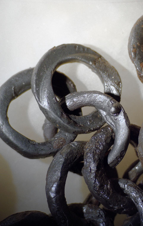
Here is a picture of a riveted ring from gjermundbu that I made a section of, then a closeup of the rivet on the same ring. The third picture is a tangential section of the rivet area of another ring. As mentioned before the rivets are slightly conical in shape, almost round in cross section.
Attachment: 128.64 KB
Section of riveted ring, gjermundbu mail
Attachment: 95.32 KB
Closeup of rivet area, plane section of riveted ring, gjermundbu mail
Attachment: 75.09 KB
Tangential section of riveted ring, gjermundbu mail
Section of riveted ring, gjermundbu mail
Closeup of rivet area, plane section of riveted ring, gjermundbu mail
Tangential section of riveted ring, gjermundbu mail
Oh that is wonderful Vegard, many thanks for sharing.
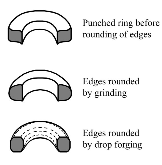
Then on to the punched rings. The rounding of the edges on mail rings after the punching generally may have been done by grinding them down as you have described doing Johan. Arne Jouttijärvi, myself and probably others have come to that conclusion, and have refered to the illustration of the ringmaker from the year 1425 in Das Hausbuch der Mendelschen Zwölfbrüderstiftung zu Nürnberg. The ringmaker seems to be a general ringmaker, and not spesifically a mail ringmaker, so it is open to discussion though.
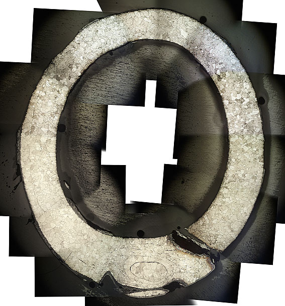
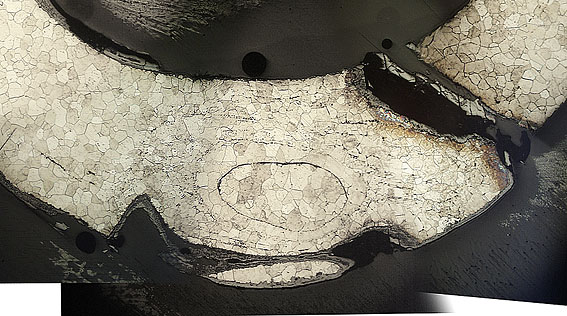
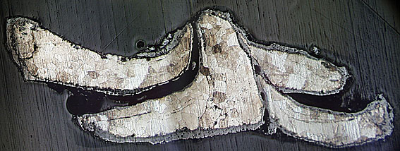
After writing my paper on the metallografic studie of three mail finds, I took a closer look at the gjermundbu mail, and found out that the rings had not been grinded, but where instead rehaped after the punching by a sort of dropforging. What gave it away was some faulty rings, especially one in particular, that had been put a squew into the shaping/dropforging tool. I think I have to give you an illustration of this, and in addition som pictures of the faulty ring, hopefully it will explain it.
[ Linked Image ]
Attachment: 61.91 KB
Rounding of edges on a punched ring
Attachment: 66.02 KB
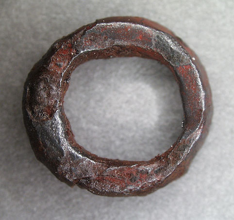
Punched ring of standard form, note the rounded shape of the edges both on the inside and outside.
Attachment: 84.5 KB
The faulty ring
Attachment: 52.53 KB
The faulty ring. Closeup.
Attachment: 176.1 KB
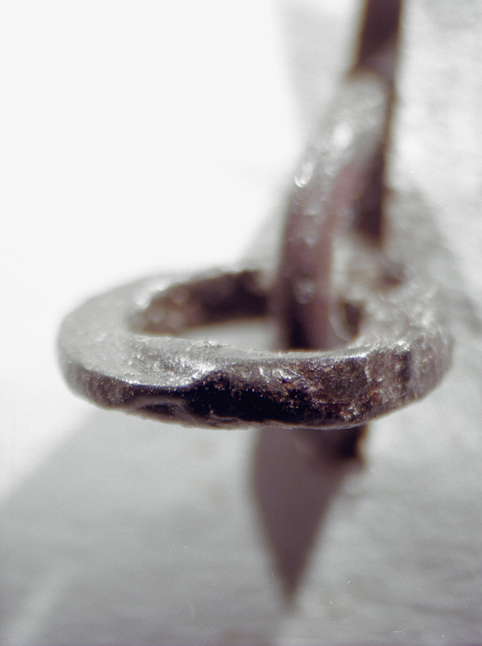
The faulty ring, seen from the edge.
Attachment: 81.3 KB
More faulty rings.
Attachment: 73.09 KB
Punching and reshaping/dropforging [ Download ]
After writing my paper on the metallografic studie of three mail finds, I took a closer look at the gjermundbu mail, and found out that the rings had not been grinded, but where instead rehaped after the punching by a sort of dropforging. What gave it away was some faulty rings, especially one in particular, that had been put a squew into the shaping/dropforging tool. I think I have to give you an illustration of this, and in addition som pictures of the faulty ring, hopefully it will explain it.
[ Linked Image ]
Rounding of edges on a punched ring
Punched ring of standard form, note the rounded shape of the edges both on the inside and outside.
The faulty ring
The faulty ring. Closeup.
The faulty ring, seen from the edge.
More faulty rings.
Punching and reshaping/dropforging [ Download ]
Last edited by Vegard Vike on Tue 30 Aug, 2011 4:18 pm; edited 2 times in total
The roman mail from Hedegård in Denmark var studied and described to reproduce its construction by Michel Kalsbøll Malfilâtre in 1993. From that publication these illustrations show the shaping of punched rings. This method is similar to the one used on the gjermundbu rings, but not exactly the same. The tool illustrated for the shaping of the Hedegård rings could not have produced the faulty ring from the gjermundbu mail.
[ Linked Image ]
Attachment: 120.69 KB
Hedegård mail. Shaping of punched rings. By Michel Kalsbøll Malfilâtre 1993 [ Download ]
[ Linked Image ]
Hedegård mail. Shaping of punched rings. By Michel Kalsbøll Malfilâtre 1993 [ Download ]
please tell me maile makers had a couple of servents...
but even if he did i can understand more fully why maile was considered such a hard to get and therefore expensive item during the dark age/ viking age/ medieval period. and why the romans made their legionaries use segmentata mostly
but if i may make a suggestion, this might be something already thought of, and i realise this is experimental work, but im wondering how possible it would be to have multiples of the solid ring puncher etc.
and one other question, are the non solid links attatched to the weave before or after they have the overlapped ends flattened? (in order to be pierced and then riveted)
| William P wrote: |
| please tell me maile makers had a couple of servents...
but even if he did i can understand more fully why maile was considered such a hard to get and therefore expensive item during the dark age/ viking age/ medieval period. and why the romans made their legionaries use segmentata mostly but if i may make a suggestion, this might be something already thought of, and i realise this is experimental work, but im wondering how possible it would be to have multiples of the solid ring puncher etc. and one other question, are the non solid links attatched to the weave before or after they have the overlapped ends flattened? (in order to be pierced and then riveted) |
I can only comment from using pre overlapped / pierced rings.
Once you start the weaving of the maille to then try and flatten and pierce with a drift prior to riveting while in the weave would be nigh on impossible and extremely time consuming. When you start doing expansions where you end up with five rings connected to a single ring rather than the normal four it can get tricky enough to place and crimp the rivet as it is.
So I would suggest that for the timeliness and also accuracy all rings would be overlapped, flattened and pierced with a drift prior to adding to the weave :)
On topic, the content of this thread is amazing, not only from the OP but also the additional information. So very educating, thanks!
Brett
i guessd thats a good point,
and now that i think of it, the drifted hole would possibly help the ends line up properly when reclosing the link after adding it to the weave.
and now that i think of it, the drifted hole would possibly help the ends line up properly when reclosing the link after adding it to the weave.
Great to see you on the forum and thank you so much Vegard!
I'm so sorry we passed each other on Wisby as I've been a great fan of your maille research ever since I first read the Brynjevev paper many years ago. But now you found the thread here instead.
Your shared insights and deailed photos are invaluable for making the rings accurately. I simply can't thank you enough! :)
I'll construct tools for drop forging the solids as soon as I'm able and I'll make sure to make some few that are misaligned even. When one has that tool it should save even more time and effort on manufacturing.
Also, funny enough I did use conical rivets first, but switched to slightly flattened very pointy triangles. I can just switch back to my frist rivet type, they were actually easier to work with.
I'll also try to make a plier or similar tool that actually gives the #5 mark at the rivet overlap. I have a leatherworkers plier that I can easily adapt as it has a removable joint screw. Much easier to get at those inner surfaces that way and it's hand forged so it looks nice already. I'm also thinking the plier jaw surfaces may need to be flat bottom and slightly concave top to get the right look as seen in the photos.
[ Linked Image ]
I'll give it a try and see how that turns out.
Could the #4 mark be from the rivet pressing tool? I don't see it on all riveted rings just some and so I'm guessing it could be the second pressing that sometimes does it if it's a little misaligned and the edge of it touches the ring.
Hi
My friend just ordered a mail with alternating solid and riveted rings from india. The solid rings he had in his mail were awfully thin. I didnt measure, but i think they were thinner than 1mm...
So how thick is the material you are punching the solids out from, and how thick are the solids in the gjermundbu maille.
Also, could you please tell if other surviving examples of mail have the same thickness for rings or are they thinner/thicker?
Sorry if you already wrote about it somewheare in the topic but i have missed it. :)
Hi Robert,
I've used 1,5 mm plate to punch from so far. Inner diameter 5 mm and outer 8, making the ring square section. Of course, I now find they also need to be drop forged to be complete.
I've used 1,5 mm plate to punch from so far. Inner diameter 5 mm and outer 8, making the ring square section. Of course, I now find they also need to be drop forged to be complete.
| Johan Gemvik wrote: |
| Hi Robert,
I've used 1,5 mm plate to punch from so far. Inner diameter 5 mm and outer 8, making the ring square section. Of course, I now find they also need to be drop forged to be complete. |
Ok, thank you.
Is the 1,5mm thickness same as the gjermundbu mail originally had? If the inner diameter is 5mm and outer 8mm than it means that the thickness is 3mm? Am i correct if i think that it makes the solid ring a little bit flat? So the cross section is wider that it is thick. (i hope you get what im trying to say here:D)
I have looked at some mail fragment finds from Estonia and they seem to be more like 10mm in outer diameter and ~~8 in inner. Ofcourse these are a bit later than gjermunbu. 11- 12 century.
For example this: https://picasaweb.google.com/117366979389819398139/Kaku#5605241442722285730
So i was thinking that what might be the reason for much bigger rings? Did the rings get bigger at later times, or is it just the lazyness of Estonian mailmakers? :D
| Robert Rootslane wrote: |
|
Is the 1,5mm thickness same as the gjermundbu mail originally had? If the inner diameter is 5mm and outer 8mm than it means that the thickness is 3mm? Am i correct if i think that it makes the solid ring a little bit flat? So the cross section is wider that it is thick. (i hope you get what im trying to say here:D) |
No. The cross section would be round or square, not flat. The internal diameter is 5mm, then, each side of the ring has 1,5mm. Both together, 3mm. The internal diameter is taken from the ring's edge, not from the center of the cross section.
By the way, This is an excelent thread. I am almost convinced to make one mail like this someday hehe
| Dan Howard wrote: |
| The mail examples that show high slag content are more than likely made from wire that hasn't been drawn. |
Dan,
You have got me curious.. Why wouldn't drawn wire exhibit slag, at least in lines? The heavy iron cables used in Victorian era bridge construction were drawn, and did have "lines" of higher concentration slag zones within the cables. The slag lines did take on an orientation as a result, so if we mean "high slag content" has slag randomly dispersed all throughout a mail ring specimen then I could see why it would make drawing processes seem unlikely.
Jared
| Vinícius Arruda wrote: | ||
No. The cross section would be round or square, not flat. The internal diameter is 5mm, then, each side of the ring has 1,5mm. Both together, 3mm. The internal diameter is taken from the ring's edge, not from the center of the cross section. By the way, This is an excelent thread. I am almost convinced to make one mail like this someday hehe |
oh....
ofcourse it is. Sounds logical now that you have said it...
However, any ideas about the larger rings by anyone?
| Jared Smith wrote: |
| You have got me curious.. Why wouldn't drawn wire exhibit slag, at least in lines? The heavy iron cables used in Victorian era bridge construction were drawn, and did have "lines" of higher concentration slag zones within the cables. The slag lines did take on an orientation as a result, so if we mean "high slag content" has slag randomly dispersed all throughout a mail ring specimen then I could see why it would make drawing processes seem unlikely. |
Are there any examples of puddled iron that has been drawn into wire as thin as that used for mail?
Robert, there's nothing preventing one from making as large punched rings as one wants really, except for punching force. Just use a bigger hammer. There are physical limits to this of course but then maille rings were never really all that huge. There are also solid links found in surviving mailles that are welded as they have an obvious seam, just like proper chain links. Doing this no doubt becomes easier with larger rings as they retain forge heat longer and have some decent material to work with the hammer. We've discussed this before in the thread.
Jared, the common idea among us maillemakers and maille historians is that high slag content makes wire break when being drawn, so either you get only short lengths free of slag (if you trim the ends off where it breaks) or you have to get the slag out before drawing the wire. Either way riveted links with no slag are the end result if they're drawn, whereas hammered wire could have all the slag you want (or don't as would be the case). This is just theory though. It's quite possible we're wrong about this but it sure seems logical to me. ;)
On that note, the iron I got now needs to be turned into wire somehow. Simple hand force drawing of steel wire was practially impossible when I tried it, which probably means drawign the iron will also be quite difficult and an improbable way for it to have been done historically.
So I was looking at tools to help drawing and came across these.
http://www.jewelerstoystore.com/Steel_Drawplate_s/416.htm
http://www.jewelerstoystore.com/Draw_Bench_p/d64.htm
http://www.jewelerstoystore.com/Draw_Tongs_p/t50-1.htm
Of course, I'd rather design and build something historically plausible for viking age and also save some $$$ doing that. ;)
I'll figure something out, being a mechanical engineer comes in handy sometimes after all, but do feel free to share your own ideas on this guys. Maybe someone has tried it already and has some leads? Maybe there are some medieval or ingenious renessance age machines illustrated somewhere that could give us a hint. Crossbow pulley systems come to mind and of course a simple mandrel might be sufficient at least for very thin wire.
Page 4 of 7
You cannot post new topics in this forumYou cannot reply to topics in this forum
You cannot edit your posts in this forum
You cannot delete your posts in this forum
You cannot vote in polls in this forum
You cannot attach files in this forum
You can download files in this forum
All contents © Copyright 2003-2006 myArmoury.com — All rights reserved
Discussion forums powered by phpBB © The phpBB Group
Switch to the Full-featured Version of the forum
Discussion forums powered by phpBB © The phpBB Group
Switch to the Full-featured Version of the forum