3 span Roman catapulta build
Hi All,

Last year I was involved in running the build on a TV show where we built a 6 span catapulta in a serious hurry. This was my first exposure to these weapons and my understanding was helped by the input from Alan Wilkins and Tom Feely and I really got the bug.

The simplicity and purity of design just hooked me and so even though I make all day for a living, I decided to make one myself, just because, and so those odd moments of spare time have recently been dedicated to making a 3 span machine and I will document some of the work here.

Catapultas are the Roman arrow shooters and were developed from early Greek artillery and they went through continuous development from their origins through to the demise of the Empire. We have been incredibly fortunate in that two sets of documents have been assembled from parts to create a partially complete set of design sizes from Philon, a Greek scholar from the 5thC BC and Vitruvius a Roman architect from the first C BC. Between these two incomplete sets of documents we have been able to reconstruct nearly all the dimensions of these machines. There are some differences between the two sets of data, but most sizes are the same and so we can use these, with a little thought and guesswork, to make pretty accurate machines.

A great deal of the development of our understanding is thanks to EW Marsden and his fantastic treatises and then the continuing works of his friends Alan, Tom and Len Morgan.

The sophisticated simplicity of these machines is what hooked me. As we all know, engineering does not directly scale up or down and yet these machines seem to.

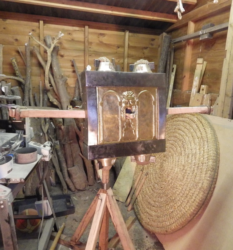
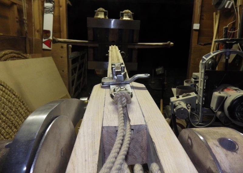
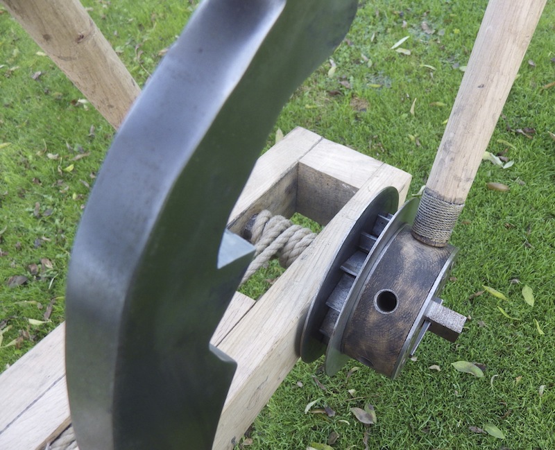
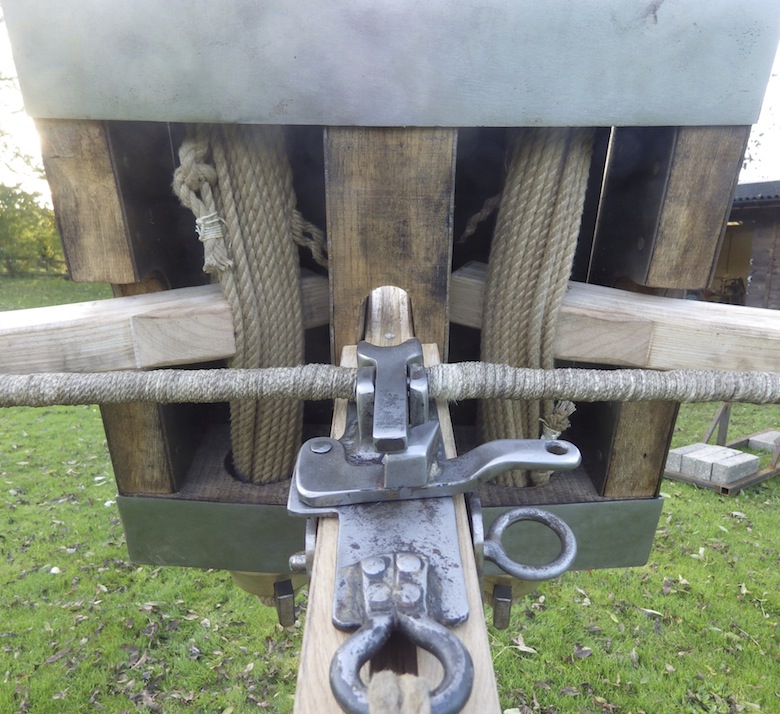
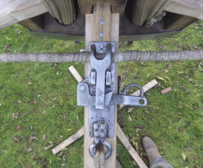
The motive power of these machines is generated by twisting two bundles of cord by drawing back the arms that pass through the centre of the bundles. By twisting the bundles you are in fact stretching them and so they want to pull back and to do this they must return the arms back to the rest position.

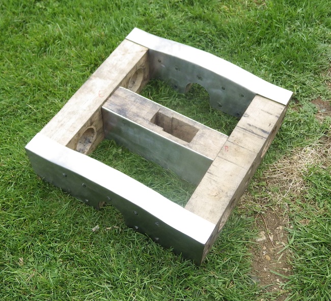
Start with the bolt size you want to shoot, divide this length by 9 and that gives you the 'hole' size. This is the size of the hole cut through the top and bottom plates of the head frame that the ropes pass through. Every dimension of the machine is a multiple of this hole size.

The Romans built machines from 1 through to 3 span, a span being 231mm and this refers to the length of the bolt, so a 3 span shoots a bolt 693mm long (28") and the therefore the hole size is 77mm.

What is lovely about this system is that an artillery officer need not even have experienced men working for him, he can just hand him a measuring stick 1 hole long, and ask for a timber 1 stick wide by 1 stick wide by 19 sticks long for example. (main stock, called the 'case' in Marsdens treatise). In fact Roman artillery officers were issued books with tables in them, so that when they arrive at a new site, a fort for example, they can pace a room and measure the ceiling height and after consulting their tables they can see what the maximum size of engine they can fit the space. Genius.

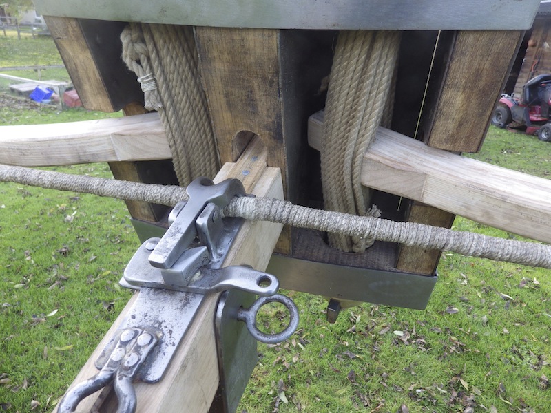
The Romans used sinew ropes for the torsion bundles and the real secret of these machines is that they were fitted to the machine and pre- tightened even before any twisting and were stretched so much, that the rope reduces to 66% of its starting diameter before the next pass of rope is fitted. By doing this, even before twisting the bundles, the arms come under enormous torque. We cannot use sinew rope and so I have used a modern synthetic that is not likely to be as efficient as sinew but still I hope for a good result.

The Romans listed the shooting distance of a 3 span machine as 440 yds, being the most efficient size. The one I made last year was a 6 span, a size the Romans never built and is likely to be pretty inefficient and it still got 319m (340yds).

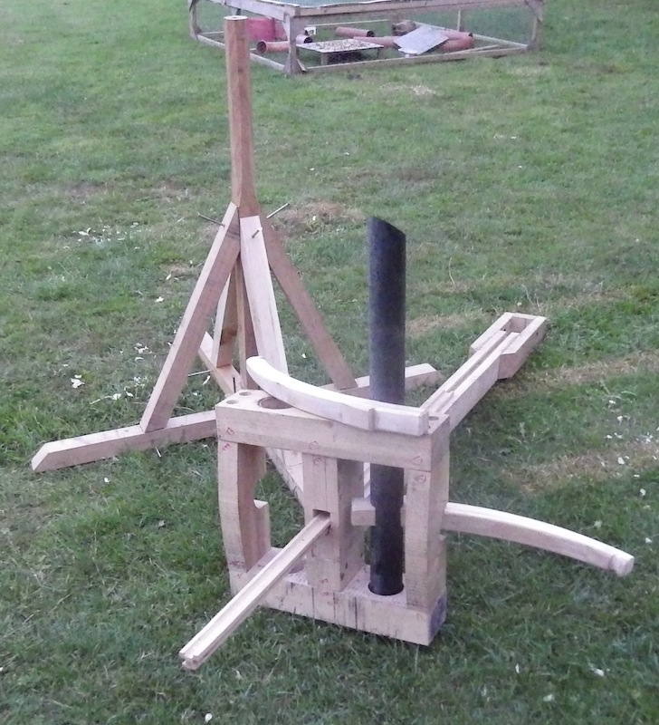
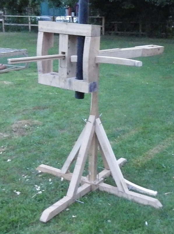
So my plans are as follows.

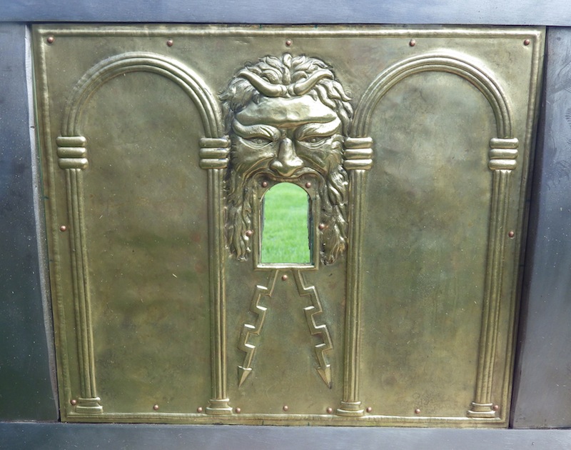
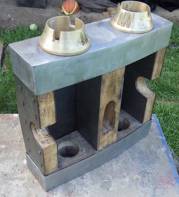
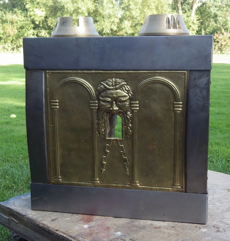
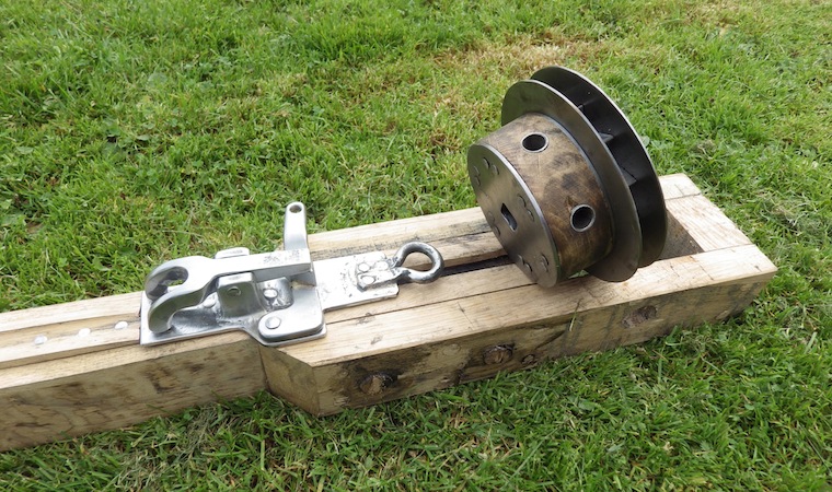
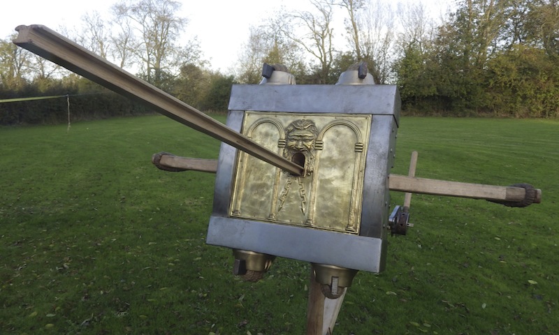
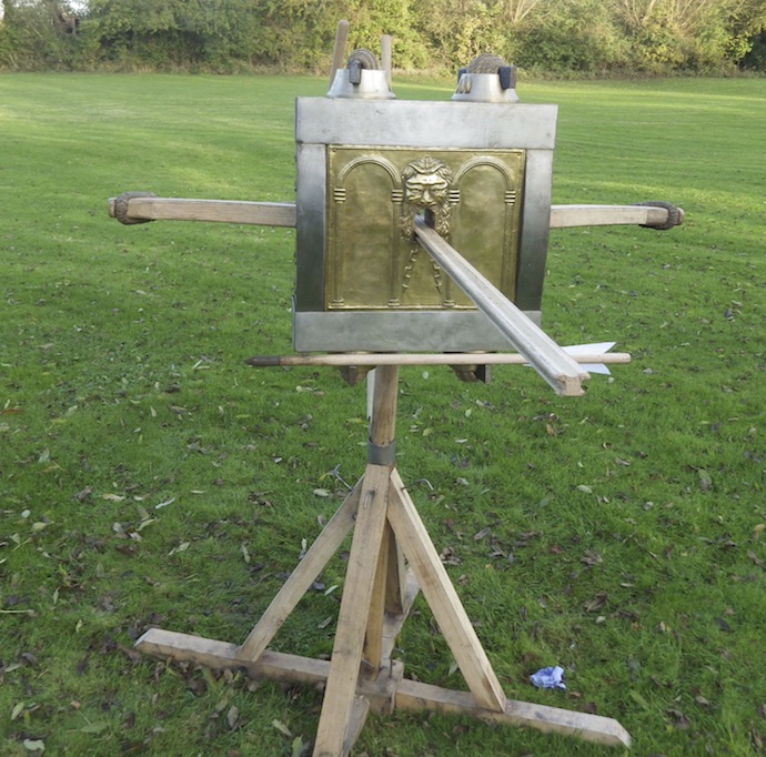
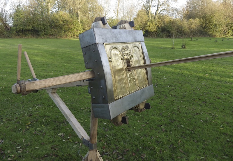
The wooden parts are all green oak, except the arms, which are laminated ash and olive, which is required to get the curvature. The curve allowed for around 30% more power as it increases the power stroke and was a later Roman innovation. The head frame will be heavily reinforced with steel and again this was a later Roman innovation and allowed for a longer lived and safer machine. The washers (top and bottom metal components used to twist the bundles) have been cast in brass and need to be machined. I will also be fitting a brass front cover plate that protects the bundles from incoming missiles and also looks impressive. I will likely make the string in Kevlar as this is a component I do not want to risk breaking.

The earlier stages of the build mainly involved cutting wood and so is not so exciting, but now that things are starting to come together I will post up pictures as I go and try to be as coherent as I can through a very detailed subject.

I hope you enjoy.

Tod


 Attachment: 205.4 KB
IMGP1681.JPG


 Attachment: 139.14 KB
IMGP1682.JPG

Amazing work, I can't wait to see it completed!
What kind of projectiles are you going to use with this machine?
Great initiative! - those torsion powered shooters of the antiquity, be it any kind of ballistas really, are fascinating indeed. So a good deal of praise to you for taking the effort to actually documenting a build of this kind Tod.

I am in complete agreement with your statement about the beauty of design - really efficient despite, or probably in part just because of the deceptive simplicity. A build like this has appeal both as an attempt of recreating a functional historical design as well as it is an ingenious contraption in its own right - thus speaks to both the passion of history as well as the engineer in me.

Rest assured that this build-along will be followed with avid interest even if it ends up spanning a longer period of time as a result of the need to earn a living in between..
-You mentioned that sinew rope cannot be used by you? Why is that?
You also mention that your replacement is probably less effective. What string material do you use and why would it be less effective? One could probably quantify these differences.

-Would it be possible to get a video of you prestretching the ropes? I find it hard to visualize in my head.

-When you spoke of the advantage of having greater power-stroke due to the curved limbs, I believe you misused the term. Power-stroke is the difference between draw length and brace height AFAIK. It would not be affected by any curvature of the limbs.
An increase in stored energy results from (if it is in any way similar to bows) the force needed to stretch the string being over-proportionally greater during the early draw. To test this and the efficacy of the build, could you produce the f/d-curve?
I am exited that I am going to see this today.
Having worked on the 6 span machine last year . I am most interested in what this will do and am fully expecting it to be quite an awesome machine.
The machine last year was a most impressive beast , despite being rushed for a fast build television show.
I am expecting good things from this build (having had a couple of sneak previews of whats coming up) and think you are going to be in for a treat.
Marc Ritz wrote
Quote:
You mentioned that sinew rope cannot be used by you? Why is that?
You also mention that your replacement is probably less effective. What string material do you use and why would it be less effective? One could probably quantify these differences.

-Would it be possible to get a video of you prestretching the ropes? I find it hard to visualize in my head.

-When you spoke of the advantage of having greater power-stroke due to the curved limbs, I believe you misused the term. Power-stroke is the difference between draw length and brace height AFAIK. It would not be affected by any curvature of the limbs.
An increase in stored energy results from (if it is in any way similar to bows) the force needed to stretch the string being over-proportionally greater during the early draw. To test this and the efficacy of the build, could you produce the f/d-curve?


I suppose the use of the word 'can't' is not quite true, it is rather that I am not prepared to make it! You cannot buy sinew rope anymore and last year I made around a meter of thin cord and it took around £5 of materials and took 2 hours. This machine will require around 31m on each side, so this would take around £1000 of materials and many, many days just for the rope.

Sinew is remarkable. It stores energy in an amazing way that is not replicated by modern ropes and the closest material we have that works in a way that we want, is pre-stretched polyester. I must confess I have not researched into the scientific differences in how the stress/strain curves of these materials differ and what that actually means in reality. The bottom line is that this is the material I was suggested and it worked damn well last time.

I will try to get a video of us stretching the ropes as they go in. This is in fact the real make or break for these machines. The cords must be laid straight and very orderly and as each pass goes in it is stretched and 'clipped' to stop it relaxing back. I will use a lever with good mechanical advantage so that each cord has a load of (estimate) 200kg on it. Each washer set will have around 25 passes of rope making up 50 cords. 50 cords x 200kg = 10 tonnes. Basically before the washers are even turned a degree the stored force is massive. To ready the machine for operation the washers are then rotated and pinned into place to stop them moving.

This means that the weight of the bow at brace is already very high.

In reference to the powerstroke. The head frame has two cutouts on either side to allow the arms to move as far forward as possible as so extend the possible powerstroke of the machine. To illustrate what I meant, imagine that if these cut out were not there the powerstroke would have to be shorter - correct?. Obviously the cutouts are there, but imagine the line made by the string if the arms were straight verses curved. Because the tips of the limbs curve forward the string rests far further forward than if the limbs were straight, as an estimate 8-10". What this means in reality is that because the arms are curved forward you get a significantly longer stroke at the end.

Additionally there is a limit to how far you can draw the string back because it will slip off the limb tips. Because the curved limb tips curve away from the case (stock) this point is reached later than if the limbs were straight.

So using curved limbs gets you more travel at the end and the start of the stroke verses using straight limbs. I don't have the exact numbers myself, but my understanding is that the Romans felt this to be a 30% improvement in distance.

I will not be able to make a full force draw curve for this bow because a load cell cannot be inserted easily into the system as you get to the longer draws but it will be able to get one on for partial draws and indeed I would love to get some sort of feel to what this bow will draw - big numbers I hope.

Owen Bush wrote
Quote:
I am exited that I am going to see this today.
Having worked on the 6 span machine last year . I am most interested in what this will do and am fully expecting it to be quite an awesome machine.
The machine last year was a most impressive beast , despite being rushed for a fast build television show.
I am expecting good things from this build (having had a couple of sneak previews of whats coming up) and think you are going to be in for a treat.


Had a nice beer sodden evening with Owen and part of that was to chat over the stringing of this machine. On the TV show last year I headed the engineering and worked very closely with Owen to string the beast we made then and so I have asked him and Steve, another engineer from the show, to come over when the time comes and help out. You need one person to feed the rope through and clip it , one to pull and keep tension on the lever and one to organise the rope for the next pass.

You cannot stop once you have started and last time it took around 8 hours a side, but that had around 100m of rope each side, this will be easier, but still some moral support is very welcome.

Last years build can be seen here http://www.youtube.com/watch?v=CgNlPOMOps0

Tod
I have started to plate the frame now and the central stanchion has been plated and through riveted and the two side stanchions have also been plated and riveted.

This system is shown very clearly on the Xanten machine and will make for a frame that is tough as hell and as I want to load the bundles on this machine until it screams, this is a good thing.

I have also plated and riveted the windlass hubs. The texts do not mention the Romans doing this, but again as I want to load the windlass levers heavily it just felt suitable to do this to ensure longevity.

The next step is to fit the front anti-missile plate and the top and bottom caps and I have something special planned for the anti-missile plate...........

Tod


 Attachment: 193.09 KB
IMGP1722.JPG


 Attachment: 192.57 KB
IMGP1725.JPG

Hi Tod,

a while back I had made a lot of horsehair rope for a project but it wasn't used so i have a good many meters in stock. If you have a project where you need it and are having trouble getting it (I had to buy horse hair in china, have it sorted elsewhere I can't recall and then woven up in Denmark) then drop me a line....

Griff
Thanks Mark.

I have made some fairly slow progress since the last post as I have had a lot to get on with but the top and bottom trays have been cut and welded up and the washers machined.

The trays look modern, but looking at the Xanten machine they were pretty much like this.

The front armour panel is steel covered in brass repousse. I went this route as many of the fronts were decorated and the screaming face of Jupiter seemed appropriate. The face was taken from a fountain and I added the thunderbolts. Much as I would like to take the credit for the repousse, I did not make this part.

The winch is underway and should be finished in the next week or so and then onto the trigger.......

Tod


 Attachment: 154.96 KB
IMGP1995.JPG


 Attachment: 169.64 KB
IMGP1996.JPG


 Attachment: 178.81 KB
IMGP1993.JPG

Veeeery cool.
Baggsy on the crew if we can take it to Maiden Castle to skewer some Britons?
Matthew, I am sure you will get to play one day, but thanks or the thoughts.

I have just finished the trigger system and made a start on the winch system - it is getting close now.

As soon as the winch is finished then I can find the balance point and get the whole lot mounted up.

And after that it is time to rope it all up!

Tod


 Attachment: 195.92 KB
IMGP2035.JPG

I have finally roped the machine up and have some more tweeking to do but so far so good.

I will post up some better pictures next week and do some testing.

Tod


 Attachment: 199.02 KB
IMGP2220.JPG


 Attachment: 118.84 KB
IMGP2221.JPG

That is outstanding Tod! Please post some Youtube video if you can when you fire it! And, please blast some pumpkins or watermelons or a big bag of flour! Something that wil make an impressive spectacle!!!!
Here are some better pictures of it.

I have been ironing out a few teething problems, adjusting string length and so on and am now happy with how it all feels. Until I draw it back fully I won't know how hard it will be, so I might have to up or down the pretension of the ropes, but at present all feels good.

I have not measured it accurately yet, but at around 12" of draw it is pulling around 250-300kgs.

Weather permitting I will have a proper shot on Thursday when I have a helper in who can help me spot as I have to shoot across a neighbouring field.

I will unfortunately not have time to mess about with it properly and do chrono tests etc on Thursday, but hopefully will get back to before too long - either way I will keep you posted.

Tod


 Attachment: 130.62 KB
IMGP2247.jpg


 Attachment: 197.3 KB
IMGP2249.jpg


 Attachment: 203.5 KB
IMGP2252.jpg


 Attachment: 188.92 KB
IMGP2254.jpg


 Attachment: 193.84 KB
IMGP2255.jpg


 Attachment: 181.78 KB
IMGP2258.jpg


 Attachment: 195.26 KB
IMGP2260.jpg


 Attachment: 176.53 KB
IMGP2263.jpg

Very, very pretty Tod..... Purposeful and aesthetically pleasing. There is something in your soul that renders you incapable of producing anything other than elegant perfection I am pleased to say.

Perhaps it needs a home somewhere up on the Roman Wall..... Coincidentally, round about where Flora and I live..... I mean it would be an interesting counterpoint to the latchet bow; the balestrino; the windlass bow ;)

Martin
I've always been fascinated by these machines. So very good to actually be able to follow the construction details. Have you had a chance yet to actually run some live fire tests ? If so, there's a couple of things I've been curious about. At the moment of firing, I'd imagine there would be a certain amount of ?forward bounce? in the arms and bowstring before it returns to it's 'rest' position. When this occurs..is there any danger of the arms actually contacting the semi-circular notches in the frame ? If this happened, I'd imagine, given all the stresses involved, there could be a danger that the sudden shock could snap the arms of the bow ?
Also the ?slider" that the arrow/bolt rests on/in as the machine is cocked seems to project a long way out beyond the front of the machine when it's fired. I'd imagine that this would be rather a vulnerable point and prone to accidental damage or breakage when the machine is not in use . Is there any practical reason for it being this long ? Does it aid in the machines accuracy ?
Ralph Grinly wrote:
I've always been fascinated by these machines. So very good to actually be able to follow the construction details. Have you had a chance yet to actually run some live fire tests ? If so, there's a couple of things I've been curious about. At the moment of firing, I'd imagine there would be a certain amount of ?forward bounce? in the arms and bowstring before it returns to it's 'rest' position. When this occurs..is there any danger of the arms actually contacting the semi-circular notches in the frame ? If this happened, I'd imagine, given all the stresses involved, there could be a danger that the sudden shock could snap the arms of the bow ?
Also the ?slider" that the arrow/bolt rests on/in as the machine is cocked seems to project a long way out beyond the front of the machine when it's fired. I'd imagine that this would be rather a vulnerable point and prone to accidental damage or breakage when the machine is not in use . Is there any practical reason for it being this long ? Does it aid in the machines accuracy ?


The slider doesn't jump forward when you trigger the machine. It starts out forward, so the catch can grab the string, and is then winched back. When the string is released, that will propel the bolt -- but the slider stays in place until you decide to reload, at which point you slide it forward again to catch the string.

One thing I've been wondering about this design for a while is if it means you can easily 'dial a power'. As the catch moves back, instead of the bowstring being drawn back to meet a fixed catch, it seems like you should be able to operate the weapon with the string drawn to any desired level of power. So you could hypothetically have a scale along one side of the body that's calibrated to shoot to a given range when the device is shot at a fixed angle, which doesn't have much practical application but is kinda cool.
Ralph Grinley wrote
Quote:
At the moment of firing, I'd imagine there would be a certain amount of ?forward bounce? in the arms and bowstring before it returns to it's 'rest' position. When this occurs..is there any danger of the arms actually contacting the semi-circular notches in the frame ? If this happened, I'd imagine, given all the stresses involved, there could be a danger that the sudden shock could snap the arms of the bow ?


When setting up the machine you set the string so that it is a little way back from the head frame and you can clearly see the size of the gap between the cut out and the arm. You then make a guess as to far how further they will move at the end of a shot and cross your fingers, because you are right that if the arms hit the cutouts under force that will be the end of them.

T. Kew wrote
Quote:
One thing I've been wondering about this design for a while is if it means you can easily 'dial a power'. As the catch moves back, instead of the bowstring being drawn back to meet a fixed catch, it seems like you should be able to operate the weapon with the string drawn to any desired level of power. So you could hypothetically have a scale along one side of the body that's calibrated to shoot to a given range when the device is shot at a fixed angle, which doesn't have much practical application but is kinda cool.


Yes absolutely you can dial a power in, but you can also do this of course with elevation. You could also use a scale on a plumb bob for angle and for that matter you could also use two sighting tubes geared together that could easily be used for range finding - totally possible in Roman times. The other option is just to use crews who know their machines well.

Tod
Hm, nice to know it's possible. Not that there's really any possible application I can think of for wanting less power. Maybe if you were wanting to arc shots through a window at a specific point on the ground below, but tha's incredibly niche.

Will you have this with you at TORM? It would make a rather lovely centerpiece for your stall (and I'd like to see it in person)
That is a beautiful and powerful looking piece of work. Thanks for sharing the steps of this adventure!

(Yes, I also want to know when you expect to shoot it.)

Page 1 of 1

Jump to:  
You cannot post new topics in this forum
You cannot reply to topics in this forum
You cannot edit your posts in this forum
You cannot delete your posts in this forum
You cannot vote in polls in this forum
You cannot attach files in this forum
You can download files in this forum


All contents © Copyright 2003-2006 myArmoury.com — All rights reserved
Discussion forums powered by phpBB © The phpBB Group
Switch to the Full-featured Version of the forum