Posts: 875 Location: Paris, France
Sat 21 Oct, 2006 6:06 am
A drawing
Hello all,
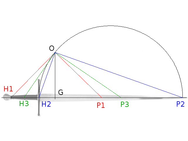
I've tried to make an illustration for pivot points and their geometrical meaning, and here is what I ended up with...
I've based the drawing on the Talhoffer, but it should be taken with a grain of salt since I don't have a really good idea of where its pivot points are... So it's mainly an illustration of the geometrical construction.
So here you have what Peter Johnsson calls forward pivot point (P2), aft pivot point (P1), and the
center of gravity G. I've added a third couple of reference/pivot point H3, P3 to illustrate the geometrical construction.
Here goes the explanation:
Let's say that we know that the pivot point associated with the cross (in H2) is P2. I've drawn it close to the tip, based on an earlier post from Peter Johnsson ("Pointy longswords will by nature therefore have a forward pivot point close to the point (at the point or a short distance behind it)..."). These two points define a segment upon which you can build a circle with diameter H2P2.
Now if you raise from G the perpendicular to the axis of the sword, it intersects the said circle at point O (like, origin since it plays a central role in the following). Note that by construction, the triangle H2 O P2 is a right triangle.
And here is the interesting bit: for any reference and pivot point H and P, this holds true, the triangle H O P is always a right triangle. I can give the mathematical demonstration of this if anyone is interested, it proceeds from the relation I wrote in my answer to Greyson.
Anyway, finding other pivot points is now easy, because it only involves building a right triangle. So for example to find the aft pivot point P1, I draw the line H1 O, and then an orthogonal line from O that intersects the axis of the weapon in P1. Same goes for any reference point... For example I've drawn the pivot point associated to the riser, here P3. I've given a different color to each of these triangles to make them stand out better.
Each distance in this diagram has a physical meaning. For example, the square of the distance OG, multiplied by the mass of the weapon, is the moment of inertia of the weapon, i.e. it measures how difficult it is to get it to rotate around G. Similarly, the square of the distance 0H1 gives the moment of inertia around H1, so that would be how difficult it is to rotate around H1... If you just use torque, that is.
And finally, you could put several weapons on the same diagram, placing them such that they share the same origin O (it's simply a matter of moving their center of gravity vertically). And then you are able to visualize simultaneously the lengths, the center of gravity, the inertia, and the pivot points, by rotating a right triangle around O. Every dynamic and geometrical properties just in one drawing...
Sadly, as far as I can figure out, the harmonic nodes cannot be represented by such simple means. So I have left them out of this...
There are other observations you can make with that. For example, note how the distance between H1 and P1 is almost the same as the distance between H3 and P3, but greatly less than the distance between H2 and P2. This means that pendulum-like motions around H1 and H3 (for example, during cutting) share some properties in speed of realignment with the motion of your arm. It would be a totally different story from H2... You could also note how the tip control properties vary greatly with just a small modification of H2... And I could go on and on :)
I hope this can help clarifying some of the complexities...
 Attachment: 18.46 KB

An illustration of the geometrical properties of pivot points
