Simulation of blade properties
Hello !

As a follow-up to two recent discussions, I have tried to go a bit further on the simulation of sword balance... The first discussion was raising the problem of the computation of CoP. The second discussion was one I started when I figured how dynamic properties and harmonic balance could be linked. In both of these threads the problem of simulation was raised, and working on this I got some interesting results I wanted to share.

I built a small Scilab program to simulate blade harmonics and dynamic properties (pivot points, center of gravity, mass), taking as inputs parameters from the materials (density, elasticity) and geometry (lengths and cross-sections). I chose a simple model for the sword, in fact one of the simplest models for slender, flexible beams (the name of the model is Euler-Bernoulli), that allows a varying cross-section along the length of the beam. The program solves the equation from the model using a 1D finite elements approach, and finds the modes of vibration, assuming that the sword is not constrained by anything. That's the best way, I think, to simulate the very relaxed grip that is assumed when looking for vibration nodes.

Being satisfied with the behavior on basic test cases (uniform bar, simple taper, and so on), I decided to go for something a bit less obvious and tried to simulate a real sword of mine: my Angus Trim type XI. To be honest, I was expecting a more or less spectacular failure :)

I measured as precisely as I could cross sections across the blade, as well as the pommel and cross-guard. I didn't want to go through the trouble of unmounting the sword so I made some reasonable guess for the tang based on what I remembered. I completely neglected the grip (I can hear the screams of horror already ;) )...

I ended up with 7 parts for the sword, over which I assumed the variation were linear, that I further subdivided in elements roughly according to their length:
* pommel (1 element)
* tang (5 elements)
* cross (1 element)
* upper part of the blade (30 elements)
* middle part of the blade (10 elements), the fuller stops here
* upper part of the blade (5 elements), not fullered
* tip (1 element)

I entered all this into the program, along with average values of density and Young modulus for steel, aft and forward positions on the grip (to compute aft and forward pivot points), and watched the results...

They are surprisingly good :cool: Figures and explanations follow...

In fact it gives the dynamic properties with a precision better than half a centimeter (far better than I can measure anyway). I just tweaked slightly the pommel shape to adjust even better (when I say slightly, it's 1mm in thickness...). And that is with all the approximation made, and a very rough model of the fuller... The harmonic nodes are also very precisely computed, from what I can see. The blade node is exactly right, the hilt node is a bit more difficult to measure, but seems to be spot-on as well.

I had to adjust the density slightly to account for the mass of the sword. My first simulation was giving a mass of 950g, while my sword weights 1011g. This uniform change does not moves the nodes or pivot points at all (this is a mathematical property of the model I use).

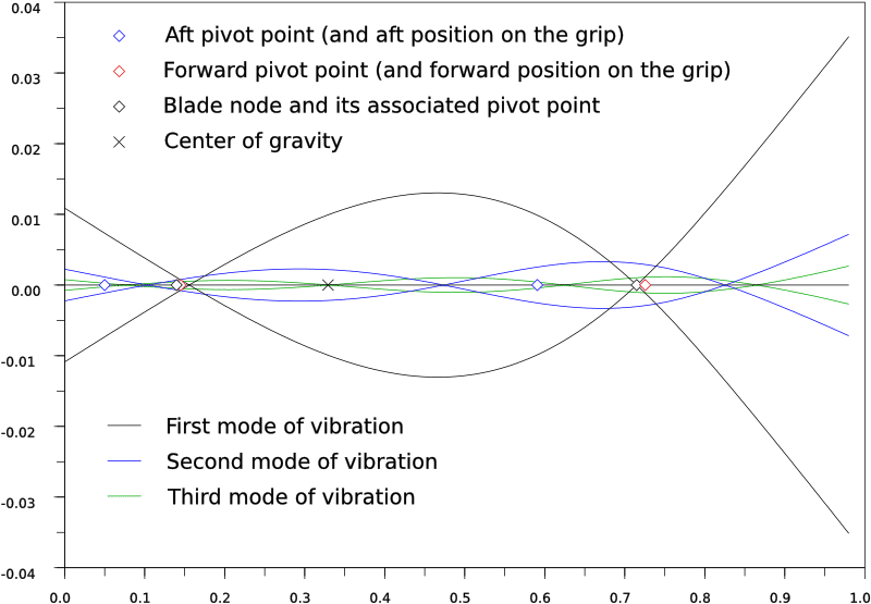
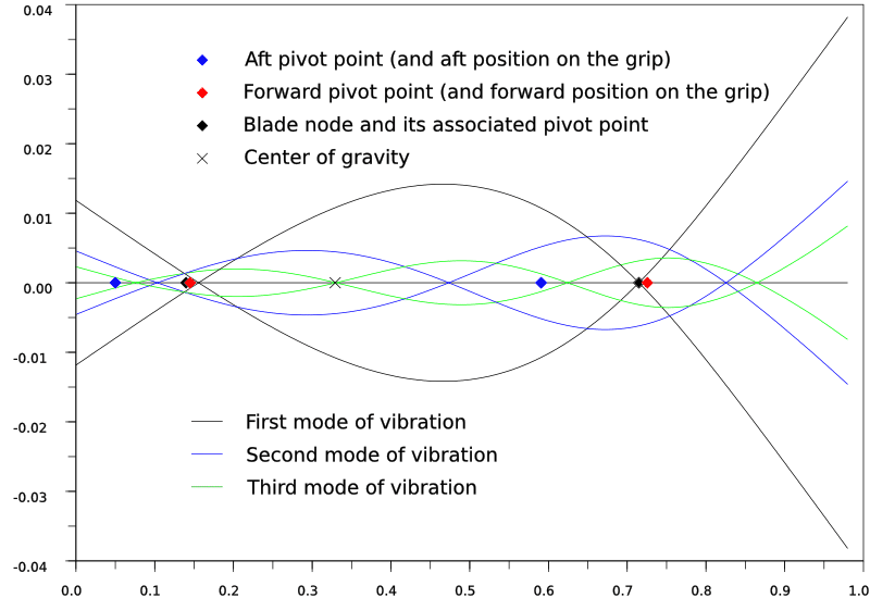
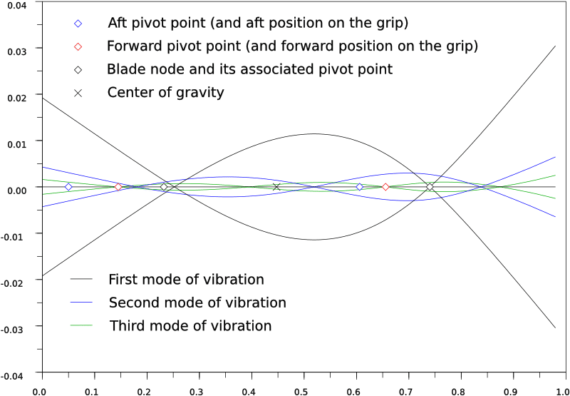
I made two figures, one with the blade alone, and the other for the full sword.

The straight black line is the axis of the undisturbed sword. The tip of the sword is to the right.

The curves represent the modes of vibration. The first mode, that is used to determine the CoP given in reviews, is in black. The curves are scaled according to the energy of the sword when it vibrates in that mode: the higher the mode, the less ample the vibration becomes. I plotted only the three first modes to keep the figure clear. For each mode, I made two symmetric curves, that indicate the deformation of the sword bending one way, then the other.

The center of gravity is marked with a black X. The aft pivot point is the blue diamond, the forward pivot point is the red one. The black diamonds are the blade node and its associated pivot point. One of my goal in doing this kind of simulation was checking how close the pivot point of the blade node was to the handle node. As you can see, they are very close indeed, less than 2cm away from each other.

On these figures appear much of the phenomenon I've heard described. Note how little the aft pivot moves between the bare and the mounted blade. This pivot point is key to the cutting motions and timing of the sword, and this shows how it depends almost on blade alone. The blade node also stays roughly at the same place between the two cases. The addition of the pommel modifies the balance by bringing the forward pivot toward the tip, the handle node toward the grip, and the center of gravity back. This diminishes the blade presence and enhances the tip feeling.

I remain convinced that the interest of such simulation is limited, because the interesting results are easily measured on swords. However, it shows what is sufficient to obtain the observed effects. It also disproves a relatively widespread idea on this matter, that it should take an army of scientists and a cluster of supercomputers to accurately model and simulate the behavior of a sword because they are somehow "infinitely complex". I must stress that I did all that using well-known mathematical methods and the simplest models, implemented in the most direct fashion, and that the core of the computation runs in about 0.1 second on my laptop (far less than what it spends plotting the results, in fact. The total is about 1s...). It proves me wrong as well, because before doing this I used to think that the number of cross sections that should be measured would have to be far greater...

Besides, the program allows for some experimentation without being a smith, which is enjoyable in its own right :) I don't know how interesting for sword makers such a program could be. I suspect not much...

I would greatly value feedback about the result, what is missing, what looks wrong... There are plenty of things I still don't quite understand about harmonic balance (for example secondary nodes), so perhaps discussion of these illustrations could clarify the matter for me and for others...

I'll also try put a cleaned up, commented Scilab code somewhere on the web if there is interest.

Kindest regards

 Attachment: 34.16 KB
bareBlade.png
Properties of the bare blade.

 Attachment: 33.98 KB
mountedBlade.png
Properties of the mounted blade.
I like this quite a bit personally. Very nice work.

Just for clarification, you might want to state what the primary plane of vibration is that you are indicating. Is this vibration in the cutting plane of the blade (usually quite stiff), or is it vibration perpendicular (ripples along the flat of the blade as I have seen several people prefer to test it?) A comparison of the two with an assumed cutting misalignment (say a couple of degrees of twist during the impact) might be worth testing in the model as representative of the relative contributions of the two different primary planes (cutting direction versus perpendicular to cutting direction) when execution is anything less than flawless. You could even add the two vectors to give a total magnitude of resultant vibration (even though the 2-D graph would not indicate specific direction locally.)

It would also be "fun" to test some things such as changing the assumed pivot point for two hand versus one hand grip.

If you decide to polish this up a little more, I would like to see better distinction (might use + sign, or some other symbols) other than color of diamonds in the legend. It is somewhat difficult for us bi-focal glasses types to see on our compact notebook computer screens!

Sincerely,
Jared
Looks nice! It would be rather unpleasant to find out that the nodes would come out all wrong, with a tool like this you can check out where they will be before you even have the steel!
Thank you both for your comments!

Bram Verbeek wrote:
It would be rather unpleasant to find out that the nodes would come out all wrong, with a tool like this you can check out where they will be before you even have the steel!


Yes, that would be a possible application. Although I'm not sure swordsmith start out straight with cross-section measurements along the blade...

In the same line of thinking, it could be used when someone starts to "design" a custom sword that they want to commission to a smith. Perhaps it could prevent obvious errors in proportions or such... Definitely not a beginner tool, though.

Jared Smith wrote:
Just for clarification, you might want to state what the primary plane of vibration is that you are indicating.


Indeed, I forgot to say that. The modes of vibration I've drawn are flat-to-flat. The main reason I started with these is that they have the biggest amplitude, so they are easy to measure on the sword, because you see the vibrations.

In fact, if the sword is ten time wider than thick, for example, the vibrations edge-to-edge are a hundred time smaller than the vibration flat-to-flat, for the same energy. Flat-to-flat they are of the order of a few centimeter, so edge to edge that's a few tenth of millimeter... I'm not even sure they are noticeable.

However the simulation is certainly possible. I suspect the nodes of the primary mode will stay more or less at the same place. I think I'll rearrange some things in the program to make it easy to have both.

Quote:
A comparison of the two with an assumed cutting misalignment (say a couple of degrees of twist during the impact) might be worth testing in the model as representative of the relative contributions of the two different primary planes (cutting direction versus perpendicular to cutting direction) when execution is anything less than flawless.


Note that I do not simulate impact. I just represent the favored modes of vibration of the blade... It does say something about the behaviour during impact, but to do what you propose I would have to model the target, the hand, the initial motion of the sword... Many variables that I cannot really measure with any accuracy. I can make guesses, of course, but even then I don't have much to compare to.

In fact I believe that the vibration we feel during a cut is indeed flat-to-flat. And this is not necessarily caused only by edge alignment being a bit off; friction within the material could be dissipated through such vibrations as well. A bit like a violin's string is stimulated by the bow. This effect is harder to simulate.

Quote:
It would also be "fun" to test some things such as changing the assumed pivot point for two hand versus one hand grip.


Well... The pivot points are properties not of the grip but of the sword. It just so happens that we grip our swords relative to special spots, for example the cross is a reference point. That's why the forward pivot is significant.

But changing the reference points for the forward and aft pivots is easy, so on a hand and a half sword you could change these and watch how the pivot points are moved on the blade. The transformation is easy to predict though, it can be deduced even without a computer, it's purely a matter of proportion.

Quote:
If you decide to polish this up a little more, I would like to see better distinction (might use + sign, or some other symbols) other than color of diamonds in the legend. It is somewhat difficult for us bi-focal glasses types to see on our compact notebook computer screens!


I can see your point ;)

I admit I've been using only the basic functions of Scilab for plotting. I'll try other symbols for comparison...

Best,
Vincent ,
now you have to take this model to the point of designing or tuning a design of a sword. the flat to flat harmonic nodal analysis is a good check to see if the model behaves realistically because you can check it against the real sword that you've modeled.

however the real use of this type of model is being able to compare it and use it in conjunction with physical observations that others have done. dynamic balance, or the sword's feel in motion, is what the model can improve upon or give a target for a new design.

you need to find radii of gyration , COP, center of oscillation (given wrist and elbow pivots), them you could go as far as torsional warping constance and air drag coefficients, all will effect the swords "feel".

having an FEA model is a great thing when designing stuff especially for stress/strain, impact energy dissipation etc., ( i use them all the time) but they are only good for mathematical horsepower, you have to have a goal and be able to use apply the data they give you to the real world (they're not always the same).

good work, can't wait see more,

Joe
Hi Joe,

Joseph Fonzi wrote:
now you have to take this model to the point of designing or tuning a design of a sword.


Designing from scratch is an overly ambitious goal, I think. Observation of antiques is probably more efficient, because they represent solutions that were proof-tested, the result of many interactions between users and smiths during centuries... This is not really something that numerical optimization can help with, it's all about context and compromises. And it won't give the aesthetics either :)

Tuning a sword to obtain properties similar to another example should be possible. It could perhaps save a few tries in steel. I don't really know, I'm not a smith ;)

Perhaps a better interface than typing numbers in a table would be in order too, with this in mind :D

Quote:
however the real use of this type of model is being able to compare it and use it in conjunction with physical observations that others have done.


That's what I'm trying to do. Unfortunately it's difficult to find complete measurements of swords, so for now I'm essentially trying on mine...

Honestly that's why I think the application of this model for vibrations will be limited. Not many people will go through the hassle of measuring cross-sections over the whole sword. Or if someone does, I expect he would be able to measure at least a pair of pivot points, and primary nodes. I really believe you don't need much more in order to start drawing conclusions about specificities in handling.

In other words, from a sword user perspective there is in fact too much info in these simulations. But at least it shows that it's feasible.

Quote:
you need to find radii of gyration , COP, center of oscillation (given wrist and elbow pivots), them you could go as far as torsional warping constance and air drag coefficients, all will effect the swords "feel".


I have the radius of gyration already (it is very tightly linked to pivot points). I haven't said a word on it, because it is not widely used (yet?) with swords... Finding the center of oscillation should be rather easy as well, the problem is agreeing on where the wrist and elbow are exactly. For all these the FEA model is not even necessary as long as you have center of gravity and moment of inertia (or equivalently a pair of pivot points), because the sword is considered as a rigid body.

COP, for swords, is commonly defined as the primary node of vibration on the blade, so I have it too. My goal with the simulation was essentially this, it is the only thing that includes deformation of the sword.

Torsion and air drag are, in my opinion, secondary effects for swords. I never really tried to impose torsion on a sword, but during handling and cutting I don't think it can become noticeable. I don't remember ever seeing a report pointing out damage to a sword by torsion... Air drag, for something as dense and thin as a sword, also has a minimal effect. I'm not saying it doesn't exist, but probably things like grip geometry have a greater effect.

Regards
Edge to edge vibrations and rat-tail tangs
Hello!

Following up to Jared's questions about which plane of vibration I was looking at, here are some results about edge-to-edge vibrations.

The current consensus is that the nodes of vibration are approximately the same whether edge-to-edge or flat-to-flat vibrations are considered. But edge-to-edge vibrations, being of small amplitude, are difficult to judge, and their effect is partly masked by that of pivot points during impacts. So that's a problem the simulation can settle.

I first ran a simulation of the mounted sword.

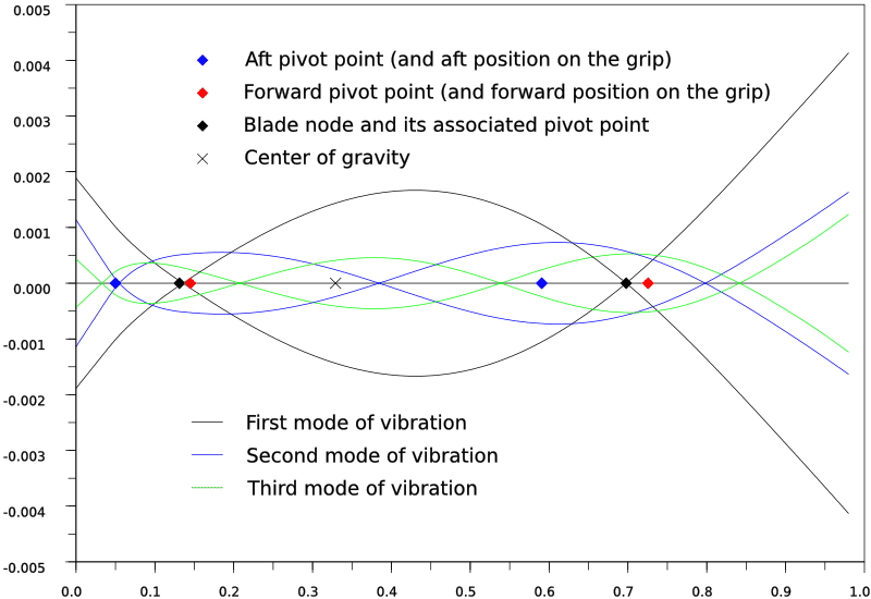
For comparison, the nodes of the first mode of vibration flat-to-flat are located at 15.6cm (handle node) and 71.5cm (blade node or CoP). The simulation gives for the first mode edge-to-edge 13.6cm (handle node) and 69.8cm (CoP). So the difference is small, perhaps not significant enough to be perceived. The pivot point associated to the CoP does not change much either: it is at 13.11cm flat-to-flat and at 13.99cm edge-to-edge. The biggest change is the shape the blade takes when vibrating. Flat-to-flat, the part of the sword close to the tang stays quite straight, because it is the thickest. Edge-to-edge, the sword tends to bend at the tang, which is thiner that the base of the blade. This is even more obvious when looking at higher modes.

These observations gave me an idea: I tried to give my sword an infamous rat-tail tang. So I divided by two the width of the tang at the point where it joins the blade. Only the profile was changed, the distal taper of the tang was not modified.

The effect on pivot points, center of gravity, and generally rigid-body dynamics is minimal. I think it could be made even less perceptible if some of the mass taken from the tang was added to the pommel. Similarly, the effect on flat-to-flat vibrations is very small. In fact when superposing the curves you would be hard pressed to tell them apart. The first mode is completely unaffected.

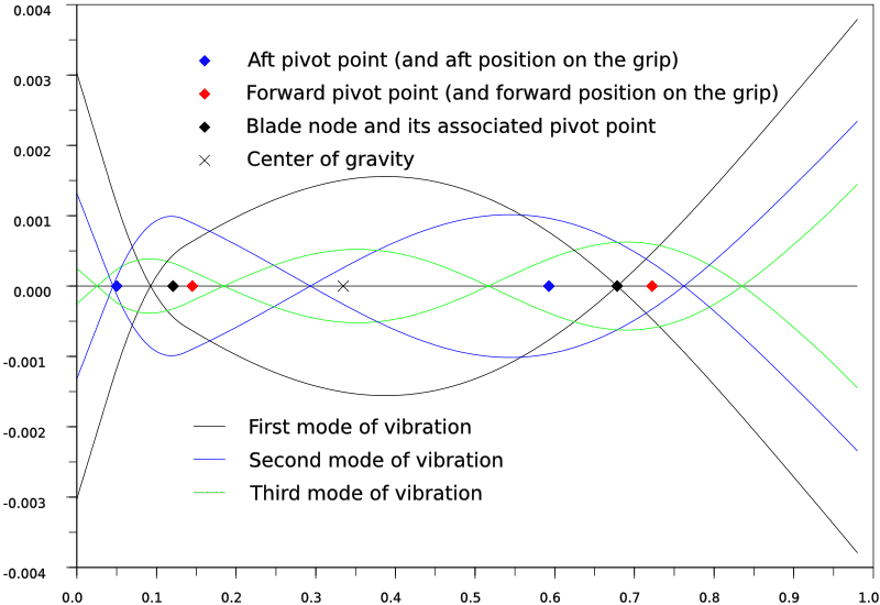
However, the effect on edge-to-edge vibrations is dramatic. The CoP moves even further back on the blade at 67.8cm. The handle node moves to 9.25cm. So just the nodes are significantly different from the flat-to-flat case of the same sword. The shape of the sword when it vibrates is downright worrying. In all the edge-to-edge modes there is a sharp bend right where the tang joins the blade. Even though the amplitude is still tenfold less than flat-to-flat, the pommel moves across a bigger distance, than with the full tang. All that would cause fatigue and stress in the tang, if it survives an impact at all...

Of course these simulations still do not tell what happens during an impact (particularly what part of the energy goes in vibrations, and what part in rigid body motion changes) but they do show something important: if we want to spot a rat-tail tang without disassembling the hilt, we have no other choice but to look at how the sword vibrates edge-to-edge. Flat-to-flat harmonics and pivot points can be completely similar between a full-tang sword and a rat-tail tang.

I include three figures: the first one is a new view of flat-to-flat harmonics for the mounted sword. The second one shows edge-to-edge harmonics on the same sword. The third shows the edge-to-edge harmonics on the rat-tail sword.

For completeness I must point out that I made an error in the previous curves, about the scaling of each mode. On the new curves the scaling is correctly done, giving the same energy to each mode of vibration. This does not affect the nodes in any way...

Kindest regards,


 Attachment: 34.47 KB
mounted-flat-fs8.png
Flat-to-flat modes of the mounted blade

 Attachment: 36.12 KB
mounted-edge-fs8.png
Edge-to-edge modes of the mounted blade

 Attachment: 38.56 KB
rat-tail-edge-fs8.png
Edge-to-edge modes of the blade with a rat-tail tang
Applause Vincent!

The new plots seem a little more crisp and easier for me to read. Either you have improved the contrast and font or I am imagining things.

I suspect the findings of the "rat tail" tang simulation are probably indicative of real phenomena. I wish to avoid naming brands, but some fairly nicely-crafted/ not-so-cheap swords with tangs best described as of this style have failed in just a few test cuts against medium hardness targets. Those searching WMA groups' videos and pictures of test cutting sessions can stumble across proof of this without too much effort.

A real swing impact (mostly edge to edge mode in cut, but imperfect alignment ) is probably a cross between the two modes.

Trying to approximate the composite affect is going to have to be subjective. Looking at water jug test cuts and the habit of sparring opponents to change alignment mid-cut (actually a good thing when done with skill and perception of the opponent), I would guess that there would be something like 80% edge-edge force, and 20% flat-flat force for a lot of people in a variety of blade contact situations. Those who both consistently cut cleanly and block very deliberately with the flat of the blade may actually get fairly pure correlation to both of your simulations. I wish I were one of those!
Thanks for your support, Jared :)

I'm glad you find the new plots more readable. The major difference is that the little diamonds are now filled instead of hollow. Perhaps the corrected scaling helps as well. The devil is in the details, I guess ;)

As you say, what is going on during cutting is quite harder to model, and I think not really useful. Free vibration modes already contain the majority of the information about how the blade deforms, and the rest will depend about as much on technique and target as on blade properties.

I'll try to comment the Scilab code, and then I will put it somewhere on the Web in the unlikely event someone would like to dig into it...

The simulations could come in handy the next time someone has a question about how such or such change in geometry or weights changes handling or harmonics, anyway...

Best,

Page 1 of 1

Jump to:  
You cannot post new topics in this forum
You cannot reply to topics in this forum
You cannot edit your posts in this forum
You cannot delete your posts in this forum
You cannot vote in polls in this forum
You cannot attach files in this forum
You can download files in this forum


All contents © Copyright 2003-2006 myArmoury.com — All rights reserved
Discussion forums powered by phpBB © The phpBB Group
Switch to the Full-featured Version of the forum